Object Attribute Memory (OAM)
The Game Boy PPU can display up to 40 movable objects (or sprites), each 8×8 or 8×16 pixels. Because of a limitation of hardware, only ten objects can be displayed per scanline. Object tiles have the same format as BG tiles, but they are taken from tile blocks 0 and 1 located at $8000-8FFF and have unsigned numbering.
Object attributes reside in the object attribute memory (OAM) at $FE00-FE9F. (This corresponds to the sprite attribute table on a TMS9918 VDP.) Each of the 40 entries consists of four bytes with the following meanings:
Byte 0 — Y Position
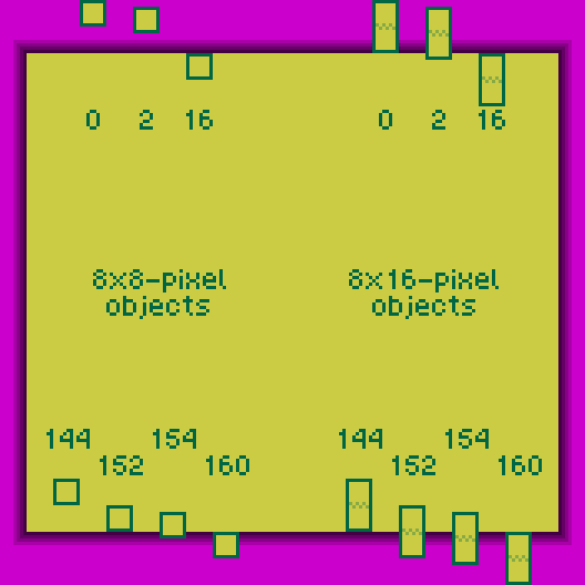
Y = Object’s vertical position on the screen + 16. So for example:
- Y=0 hides an object,
- Y=2 hides an 8×8 object but displays the last two rows of an 8×16 object,
- Y=16 displays an object at the top of the screen,
- Y=144 displays an 8×16 object aligned with the bottom of the screen,
- Y=152 displays an 8×8 object aligned with the bottom of the screen,
- Y=154 displays the first six rows of an object at the bottom of the screen,
- Y=160 hides an object.
Byte 1 — X Position
X = Object’s horizontal position on the screen + 8. This works similarly to the examples above, except that the width of an object is always 8. An off-screen value (X=0 or X>=168) hides the object, but the object still contributes to the limit of ten objects per scanline. This can cause objects later in OAM not to be drawn on that line. A better way to hide an object is to set its Y-coordinate off-screen.
Byte 2 — Tile Index
In 8×8 mode (LCDC bit 2 = 0), this byte specifies the object’s only tile index ($00-$FF). This unsigned value selects a tile from the memory area at $8000-$8FFF. In CGB Mode this could be either in VRAM bank 0 or 1, depending on bit 3 of the following byte. In 8×16 mode (LCDC bit 2 = 1), the memory area at $8000-$8FFF is still interpreted as a series of 8×8 tiles, where every 2 tiles form an object. In this mode, this byte specifies the index of the first (top) tile of the object. This is enforced by the hardware: the least significant bit of the tile index is ignored; that is, the top 8×8 tile is “NN & $FE”, and the bottom 8×8 tile is “NN | $01”.
Byte 3 — Attributes/Flags
| 7 | 6 | 5 | 4 | 3 | 2 | 1 | 0 | |
|---|---|---|---|---|---|---|---|---|
| Attributes | Priority | Y flip | X flip | DMG palette | Bank | CGB palette | ||
- Priority:
0= No,1= BG and Window color indices 1–3 are drawn over this OBJ - Y flip:
0= Normal,1= Entire OBJ is vertically mirrored - X flip:
0= Normal,1= Entire OBJ is horizontally mirrored - DMG palette [Non CGB Mode only]:
0= OBP0,1= OBP1 - Bank [CGB Mode Only]:
0= Fetch tile from VRAM bank 0,1= Fetch tile from VRAM bank 1 - CGB palette [CGB Mode Only]: Which of OBP0–7 to use
Writing data to OAM
The recommended method is to write the data to a buffer in normal RAM (typically WRAM) first, then to copy that buffer to OAM using the DMA transfer functionality.
While it is also possible to write data directly to the OAM area by accessing it normally, this only works during the HBlank and VBlank periods.
Object Priority and Conflicts
There are two kinds of “priorities” as far as objects are concerned. The first one defines which objects are ignored when there are more than 10 on a given scanline. The second one decides which object is displayed on top when some overlap (the Game Boy being a 2D console, there is no Z coordinate).
Selection priority
During each scanline’s OAM scan, the PPU compares LY
(using LCDC bit 2 to determine their size) to each
object’s Y position to select up to 10 objects to be drawn on that line.
The PPU scans OAM sequentially (from $FE00 to $FE9F), selecting the first (up to)
10 suitably-positioned objects.
Since the PPU only checks the Y coordinate to select objects, even off-screen objects count towards the 10-objects-per-scanline limit. Merely setting an object’s X coordinate to X = 0 or X ≥ 168 (160 + 8) will hide it, but it will still count towards the limit, possibly causing another object later in OAM not to be drawn. To keep off-screen objects from affecting on-screen ones, make sure to set their Y coordinate to Y = 0 or Y ≥ 160 (144 + 16). (Y ≤ 8 also works if object size is set to 8×8.)
Drawing priority
When opaque pixels from two different objects overlap, which pixel ends up being displayed is determined by another kind of priority: the pixel belonging to the higher-priority object wins. However, this priority is determined differently when in CGB mode.
- In Non-CGB mode, the smaller the X coordinate, the higher the priority. When X coordinates are identical, the object located first in OAM has higher priority.
- In CGB mode, only the object’s location in OAM determines its priority. The earlier the object, the higher its priority.
Interaction with "BG over OBJ" flag
Object drawing priority and “BG over OBJ” interact in a non-intuitive way.
Internally, the PPU first resolves priority between objects to pick an “object pixel”, which is the first non-transparent pixel encountered when iterating over objects sorted by their drawing priority. The “BG over OBJ” attribute is never considered in this process.
Only after object priority is resolved, the “object pixel” has the “BG over OBJ” attribute of its object checked to determine whether it should be drawn over the background. This means that an object with a higher priority but with “BG over OBJ” enabled will sort of “mask” lower-priority objects, even if those have “BG over OBJ” disabled.
This can be exploited to only hide parts of an object behind the background (video demonstration). A similar behaviour can be seen on the NES.
In CGB Mode, BG vs. OBJ priority is declared in more than one register, please see this page for more details.