Home
👋 Welcome to gb-asm-tutorial! This tutorial will teach you how to make games for the Game Boy and Game Boy Color.
While the Game Boy and Game Boy Color are almost the same console, the Game Boy Advance is entirely different. However, the GBA is able to run GB and GBC games! If you are looking to program GBC games and run them on a GBA, you’re at the right place; however, if you want to make games specifically for the GBA, please check out the Tonc tutorial instead.
Controls
There are some handy icons near the top of your screen!
- The “burger” toggles the navigation side panel;
- The brush allows selecting a different color theme;
- The magnifying glass pops up a search bar;
- The world icon lets you change the language of the tutorial;
- The printer gives a single-page version of the entire tutorial, which you can print if you want;
- The GitHub icon links to the tutorial’s source repository;
- The edit button allows you to suggest changes to the tutorial, provided that you have a GitHub account.
Additionally, there are arrows to the left and to the right of the page (they are at the bottom instead on mobile) to more easily navigate to the next page.
With that said, you can get started by simply navigating to the following page :)
Authors
The tutorial was written by Eldred “ISSOtm” Habert, Evie, Antonio Vivace, LaroldsJubilantJunkyard and other contributors.
Contributing
You can provide feedback or send suggestions in the form of Issues on the GitHub repository.
We’re also looking for help for writing new lessons and improving the existing ones! You can go through the Issues to see what needs to be worked on and send Pull Requests!
You can also help translating the tutorial on Crowdin.
Licensing
In short:
- Code within the tutorial is essentially public domain, meaning that you are allowed to copy it freely without restrictions.
- You are free to copy the tutorial’s contents (prose, diagrams, etc.), modify them, and share that, but you must give credit and license any copies under the same license.
- This site’s source code can be freely copied, but you must give a license and copyright notice.
Full details, please follow these links for more information on the respective licenses:
- All the code contained within the tutorial itself is licensed under CC0. To the extent possible under law, all copyright and related or neighboring rights to code presented within GB ASM Tutorial have been waived.
- The contents (prose, images, etc.) of this tutorial are licensed under a Creative Commons Attribution-ShareAlike 4.0 International License.
- Code used to display and format the site is licensed under the MIT License unless otherwise specified.
Roadmap
The tutorial is split into three parts. We strongly advise you go through the tutorial in order!
In Part Ⅰ, we run our first “Hello World!” program, which we then dissect to learn what makes the Game Boy tick.
In Part Ⅱ, we program our first game, a clone of Arkanoid; we learn how to prod the hardware into having something we can call a “game”. Along the way, we will make plenty of mistakes, so we can learn how to debug our code.
And finally, Part Ⅲ is about “advanced” use of the hardware, where we learn how to make even better-looking games, and we program a Shoot ’Em Up!
This tutorial is a work in progress.
Help
We hope this tutorial will work for you.
But if it doesn’t (the format may not work well for everyone, and that’s okay), we encourage to look at some other resources, which might work better for you.
It’s also fine to take a break from time to time; feel free to read at your own pace.
If you are stuck in a certain part of the tutorial, want some advice, or just wish to chat with us, the GBDev community chat is the place to go!
The authors actively participate there so don’t be afraid to ask questions!
The #asm channel should be the most appropriate to discuss the tutorial.
If you prefer email, you can reach us at tutorial@<domain>, where you replace <domain> with this website’s domain name.
Anti-spam measure, I hope you understand.
Setup
First, we should set up our dev environment. We will need:
- A POSIX environment
- RGBDS v0.5.1 (though v0.5.0 should be compatible)
- GNU Make (preferably a recent version)
- A code editor
- A debugging emulator
❓😕
The following install instructions are provided on a “best-effort” basis, but may be outdated, or not work for you for some reason. Don’t worry, we’re here to help: ask away, and we’ll help you with installing everything!
Tools
Linux & macOS
Good news: you’re already fulfilling step 1! You just need to install RGBDS, and maybe update GNU Make.
macOS
At the time of writing this, macOS (up to 11.0, the current latest release) ships a very outdated GNU Make.
You can check it by opening a terminal, and running make --version, which should indicate “GNU Make” and a date, among other things.
If your Make is too old, you can update it using Homebrew’s formula make.
At the time of writing, this should print a warning that the updated Make has been installed as gmake; you can either follow the suggestion to use it as your “default” make, or use gmake instead of make in this tutorial.
Linux
Once RGBDS is installed, open a terminal and run make --version to check your Make version (which is likely GNU Make).
If make cannot be found, you may need to install your distribution’s build-essentials.
Windows
The modern tools we’ll be using for Game Boy development have been designed for a Unix environment, so setup on Windows is not fully straightfoward. However, it’s possible to install an environment that will provide everything we need.
On Windows 10 and Windows 11, your best bet is WSL, which is a method for running a Linux distribution within Windows. Install WSL, then a distribution of your choice (pick Ubuntu if unsure), and then follow these steps again, but for the Linux distribution you installed.
If WSL is not an option, you can use MSYS2 or Cygwin instead; then check out RGBDS’ Windows install instructions. As far as I’m aware, both of these provide a sufficiently up-to-date version of GNU Make.
If you have programmed for other consoles, such as the GBA, check if MSYS2 isn’t already installed on your machine. This is because devkitPro, a popular homebrew development bundle, includes MSYS2.
Code editor
Any code editor is fine; I personally use Sublime Text with its RGBDS syntax package; however, you can use any text editor, including Notepad, if you’re crazy enough. Awesome GBDev has a section on syntax highlighting packages, see there if your favorite editor supports RGBDS.
Emulator
Using an emulator to play games is one thing; using it to program games is another. The two aspects an emulator must fulfill to allow an enjoyable programming experience are:
- Debugging tools:
When your code goes haywire on an actual console, it’s very difficult to figure out why or how.
There is no console output, no way to
gdbthe program, nothing. However, an emulator can provide debugging tools, allowing you to control execution, inspect memory, etc. These are vital if you want GB dev to be fun, trust me! - Good accuracy:
Accuracy means “how faithful to the original console something is”.
Using a bad emulator for playing games can work (to some extent, and even then…), but using it for developing a game makes it likely to accidentally render your game incompatible with the actual console.
For more info, read this article on Ars Technica (especially the
An emulator for every game
section at the top of page 2). You can compare GB emulator accuracy on Daid’s GB-emulator-shootout.
The emulator I will be using for this tutorial is Emulicious. Users on all OSes can install the Java runtime to be able to run it. Other debugging emulators are available, such as Mesen2, BGB (Windows/Wine only), SameBoy (graphical interface on macOS only); they should have similar capabilities, but accessed through different menu options.
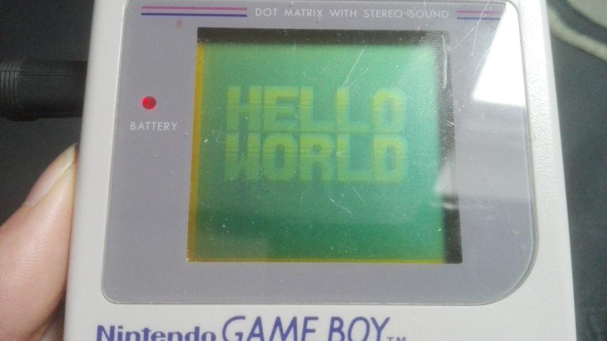
Hello World!
In this lesson, we will begin by assembling our first program. The rest of this chapter will be dedicated to explaining how and why it works.
Note that we will need to type a lot of commands, so open a terminal now.
It’s a good idea to create a new directory (mkdir gb_hello_world, for example, then cd gb_hello_world to enter the new directory).
Grab the following files (right-click each link, “Save Link As…”), and place them all in this new directory:
Then, still from a terminal within that directory, run the following three commands.
CONVENTION
To make it clear where each command begins, they are preceded by a $ symbol. However, do not type it when entering them in your shell!
rgbasm -o hello-world.o hello-world.asm
rgblink -o hello-world.gb hello-world.o
rgbfix -v -p 0xFF hello-world.gb
‼️
Be careful with arguments! Some options, such as -o here, use the argument after them as a parameter:
rgbasm -o hello-world.asm hello-world.owon’t work (and may corrupthello-world.asm!)rgbasm hello-world.asm -o hello-world.owill work
If you need whitespace within an argument, you must quote it:
rgbasm -o hello world.o hello world.asmwon’t workrgbasm -o "hello world.o" "hello world.asm"will work
It should look like this:
(If you encounter an error you can’t figure out by yourself, don’t be afraid to ask us! We’ll sort it out.)
Congrats!
You just assembled your first Game Boy ROM!
Now, we just need to run it; open Emulicious, then go “File”, then “Open File”, and load hello-world.gb.
You could also take a flash cart (I use the EverDrive GB X5, but there are plenty of alternatives), load up your ROM onto it, and run it on an actual console!
Well, now that we have something working, it’s time to peel back the curtains…
The toolchain
So, in the previous lesson, we built a nice little “Hello World!” ROM. Now, let’s find out exactly what we did.
RGBASM and RGBLINK
Let’s begin by explaining what rgbasm and rgblink do.
RGBASM is an assembler.
It is responsible for reading the source code (in our case, hello-world.asm and hardware.inc), and generating blocks of code with some “holes”.
RGBASM does not always have enough information to produce a full ROM, so it does most of the work, and stores its intermediary results in what’s known as object files (hence the .o extension).
RGBLINK is a linker. Its job is taking object files (or, like in our case, just one), and “linking” them into a ROM, which is to say: filling the aforementioned “holes”. RGBLINK’s purpose may not be obvious with programs as simple as this Hello World, but it will become much clearer in Part Ⅱ.
So: Source code → rgbasm → Object files → rgblink → ROM, right?
Well, not exactly.
RGBFIX
RGBLINK does produce a ROM, but it’s not quite usable yet. See, actual ROMs have what’s called a header. It’s a special area of the ROM that contains metadata about the ROM; for example, the game’s name, Game Boy Color compatibility, and more. For simplicity, we defaulted a lot of these values to 0 for the time being; we’ll come back to them in Part Ⅱ.
However, the header contains three crucial fields:
- The Nintendo logo,
- the ROM’s size,
- and two checksums.
When the console first starts up, it runs a little program known as the boot ROM, which reads and draws the logo from the cartridge, and displays the little boot animation. When the animation is finished, the console checks if the logo matches a copy that it stores internally; if there is a mismatch, it locks up! And, since it locks up, our game never gets to run… 😦 This was meant as an anti-piracy measure; however, that measure has since then been ruled as invalid, so don’t worry, we are clear! 😄
Similarly, the boot ROM also computes a checksum of the header, supposedly to ensure that it isn’t corrupted. The header also contains a copy of this checksum; if it doesn’t match what the boot ROM computed, then the boot ROM also locks up!
The header also contains a checksum over the whole ROM, but nothing ever uses it. It doesn’t hurt to get it right, though.
Finally, the header also contains the ROM’s size, which is required by emulators and flash carts.
RGBFIX’s role is to fill in the header, especially these 3 fields, which are required for our ROM to be guaranteed to run fine.
The -v option instructs RGBFIX to make the header valid, by injecting the Nintendo logo and computing the two checksums.
The -p 0xFF option instructs it to pad the ROM to a valid size, and set the corresponding value in the “ROM size” header field.
Alright!
So the full story is: Source code → rgbasm → Object files → rgblink → “Raw” ROM → rgbfix → “Fixed” ROM.
Good.
You might be wondering why RGBFIX’s functionality hasn’t been included directly in RGBLINK.
There are some historical reasons, but RGBLINK can also be used to produce things other than ROMs (especially via the -x option), and RGBFIX is sometimes used without RGBLINK anywhere in sight.
File names
Note that RGBDS does not care at all about the files’ extensions.
Some people call their source code .s, for example, or their object files .obj.
The file names don’t matter, either; it’s just practical to keep the same name.
Binary and hexadecimal
Before we talk about the code, a bit of background knowledge is in order. When programming at a low level, understanding of binary and hexadecimal is mandatory. Since you may already know about both of these, a summary of the RGBDS-specific information is available at the end of this lesson.
So, what’s binary? It’s a different way to represent numbers, in what’s called base 2. We’re used to counting in base 10, so we have 10 digits: 0, 1, 2, 3, 4, 5, 6, 7, 8, and 9. Here’s how digits work:
  42 =                       4 × 10   + 2
     =                       4 × 10^1 + 2 × 10^0
                                  ↑          ↑
    These tens come from us counting in base 10!

1024 = 1 × 1000 + 0 × 100  + 2 × 10   + 4
     = 1 × 10^3 + 0 × 10^2 + 2 × 10^1 + 4 × 10^0
       ↑          ↑          ↑          ↑
And here we can see the digits that make up the number!
CONVENTION
^ here means “to the power of”, where X^N is equal to multiplying X with itself N times, and X ^ 0 = 1.
Decimal digits form a unique decomposition of numbers in powers of 10 (decimal is base 10, remember?). But why stop at powers of 10? We could use other bases instead, such as base 2. (Why base 2 specifically will be explained later.)
Binary is base 2, so there are only two digits, called bits: 0 and 1. Thus, we can generalize the principle outlined above, and write these two numbers in a similar way:
  42 =                                                    1 × 32  + 0 × 16  + 1 × 8   + 0 × 4   + 1 × 2   + 0
     =                                                    1 × 2^5 + 0 × 2^4 + 1 × 2^3 + 0 × 2^2 + 1 × 2^1 + 0 × 2^0
                                                              ↑         ↑         ↑         ↑         ↑         ↑
                                          And since now we're counting in base 2, we're seeing twos instead of tens!

1024 = 1 × 1024 + 0 × 512 + 0 × 256 + 0 × 128 + 0 × 64  + 0 × 32  + 0 × 16  + 0 × 8   + 0 × 4   + 0 × 2   + 0
     = 1 × 2^10 + 0 × 2^9 + 0 × 2^8 + 0 × 2^7 + 0 × 2^6 + 0 × 2^5 + 0 × 2^4 + 0 × 2^3 + 0 × 2^2 + 0 × 2^1 + 0 × 2^0
       ↑          ↑         ↑         ↑         ↑         ↑         ↑         ↑         ↑         ↑         ↑
So, by applying the same principle, we can say that in base 2, 42 is written as 101010, and 1024 as 10000000000.
Since you can’t tell ten (decimal 10) and two (binary 10) apart, RGBDS assembly has binary numbers prefixed by a percent sign: 10 is ten, and %10 is two.
Okay, but why base 2 specifically? Rather conveniently, a bit can only be 0 or 1, which are easy to represent as “ON” or “OFF”, empty or full, etc! If you want, at home, to create a one-bit memory, just take a box. If it’s empty, it stores a 0; if it contains something, it stores a 1. Computers thus primarily manipulate binary numbers, and this has a slew of implications, as we will see throughout this entire tutorial.
Hexadecimal
To recap, decimal isn’t practical for a computer to work with, instead relying on binary (base 2) numbers. Okay, but binary is really impractical to work with. Take %10000000000, aka 2048; when in decimal only 4 digits are required, binary instead needs 12! And, did you notice that I actually wrote one zero too few? Fortunately, hexadecimal is here to save the day! 🦸
Base 16 works just the same as every other base, but with 16 digits, called nibbles: 0, 1, 2, 3, 4, 5, 6, 7, 8, 9, A, B, C, D, E, and F.
  42 =            2 × 16   + 10
     =            2 × 16^1 + A × 16^0

1024 = 4 × 256  + 0 × 16   + 0
     = 4 × 16^2 + 0 × 16^1 + 0 × 16^0
Like binary, we will use a prefix to denote hexadecimal, namely $.
So, 42 = $2A, and 1024 = $400.
This is much more compact than binary, and slightly more than decimal, too; but what makes hexadecimal very interesting is that one nibble corresponds exactly to 4 bits!
| Nibble | Bits |
|---|---|
| $0 | %0000 |
| $1 | %0001 |
| $2 | %0010 |
| $3 | %0011 |
| $4 | %0100 |
| $5 | %0101 |
| $6 | %0110 |
| $7 | %0111 |
| $8 | %1000 |
| $9 | %1001 |
| $A | %1010 |
| $B | %1011 |
| $C | %1100 |
| $D | %1101 |
| $E | %1110 |
| $F | %1111 |
This makes it very easy to convert between binary and hexadecimal, while retaining a compact enough notation. Thus, hexadecimal is used a lot more than binary. And, don’t worry, decimal can still be used 😜
(Side note: one could point that octal, i.e. base 8, would also work for this; however, we will primarily deal with units of 8 bits, for which hexadecimal works much better than octal. RGBDS supports octal via the & prefix, but I have yet to see it used.)
If you’re having trouble converting between decimal and binary/hexadecimal, check whether your favorite calculator program has a ‘programmer’ mode or a way to convert between bases.
Summary
- In RGBDS assembly, the hexadecimal prefix is
$, and the binary prefix is%. - Hexadecimal can be used as a “compact binary” notation.
- Using binary or hexadecimal is useful when individual bits matter; otherwise, decimal works just as well.
- For when numbers get a bit too long, RGBASM allows underscores between digits (
123_465,%10_1010,$DE_AD_BE_EF, etc.)
Registers
Alright! Now that we know what bits are, let’s talk about how they’re used. Don’t worry, this is mostly preliminary work for the next section, where we will—finally!—look at the code 👀
First, if you opened Emulicious, you have been greeted with just the Game Boy screen. So, it’s time we pop the debugger open! Go to “Tools”, then click “Debugger”, or press F1. Then in the debugger’s menu, click “View”, then click “Show Addresses”
The debugger may look intimidating at first, but don’t worry, soon we’ll be very familiar with it! For now, let’s focus on this small box near the top-right, the register viewer.
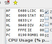
⚠️
The register viewer shows both CPU registers and some hardware registers. This lesson will only deal with CPU registers, so that’s why we will be ignoring some of these entries here.
What are CPU registers? Well, imagine you’re preparing a cake. You will be following a recipe, whose instructions may be “melt 125g of chocolate and 125g of butter, blend with 2 eggs” and so on. You will fetch some ingredients from the fridge as needed, but you don’t cook inside the fridge; for that, you have a small workspace.
Registers are pretty much the CPU’s workspace. They are small, tiny chunks of memory embedded directly in the CPU (only 10 bytes for the Game Boy’s CPU, and even modern CPUs have less than a kilobyte if you don’t count SIMD registers). Operations are not performed directly on data stored in memory, which would be equivalent to breaking eggs directly inside our fridge, but they are performed on registers.
ℹ️
There are exceptions to this rule, like many other “rules” I will give in this tutorial; I will paper over them to keep the mental complexity reasonable, but don’t treat my word as gospel either.
General-purpose registers
CPU registers can be placed into two categories: general-purpose and special-purpose. A “general-purpose” register (GPR for short) can be used for storing arbitrary integer numbers. Some GPRs are special nonetheless, as we will see later; but the distinction is “can I store arbitrary integers in it?”.
I won’t introduce special-purpose registers quite yet, as their purpose wouldn’t make sense yet. Rather, they will be discussed as the relevant concepts are introduced.
The Game Boy CPU has seven 8-bit GPRs: a, b, c, d, e, h, and l.
“8-bit” means that, well, they store 8 bits.
Thus, they can store integers from 0 to 255 (%1111_1111 aka $FF).
a is the accumulator, and we will see later that it can be used in special ways.
A special feature is that these registers, besides a, are paired up, and the pairs can be treated as the 16-bit registers bc, de, and hl.
The pairs are not separate from the individual registers; for example, if d contains 192 ($C0) and e contains 222 ($DE), then de contains 49374 ($C0DE) = 192 × 256 + 222.
The other pairs work similarly.
Modifying de actually modifies both d and e at the same time, and modifying either individually also affects the pair.
How do we modify registers?
Let’s see how, with our first assembly instructions!
Assembly basics
Alright, now that we know what the tools do, let’s see what language RGBASM speaks.
I will take a short slice of the beginning of hello-world.asm, so that we agree on the line numbers, and you can get some syntax highlighting even if your editor doesn’t support it.
INCLUDE "hardware.inc"

SECTION "Header", ROM0[$100]

	jp EntryPoint

	ds $150 - @, 0 ; Make room for the header

EntryPoint:
	; Shut down audio circuitry
	ld a, 0
	ld [rNR52], a
Let’s analyze it. Note that I will be ignoring a lot of RGBASM’s functionality; if you’re curious to know more, you should wait until parts II and III, or read the docs.
Comments
We’ll start with line 10, which should appear gray above.
Semicolons ; denote comments.
Everything from a semicolon to the end of the line is ignored by RGBASM.
As you can see on line 7, comments need not be on an otherwise empty line.
Comments are a staple of every good programming language; they are useful to give context as to what code is doing. They’re the difference between “Pre-heat the oven at 180 °C” and “Pre-heat the oven at 180 °C, any higher and the cake would burn”, basically. In any language, good comments are very useful; in assembly, they play an even more important role, as many common semantic facilities are not available.
Instructions
Assembly is a very line-based language. Each line can contain one of two things:
- a directive, which instructs RGBASM to do something, or
- an instruction1, which is written directly into the ROM.
We will talk about directives later, for now let’s focus on instructions: for example, in the snippet above, we will ignore lines 1 (INCLUDE), 7 (ds), and 3 (SECTION).
To continue the cake-baking analogy even further, instructions are like steps in a recipe. The console’s processor (CPU) executes instructions one at a time, and that… eventually does something! Like baking a cake, drawing a “Hello World” image, or displaying a Game Boy programming tutorial! *wink* *wink*
Instructions have a mnemonic, which is a name they are given, and operands, which indicate what they should act upon. For example, in “melt the chocolate and butter in a saucepan”, the whole sentence would be the instruction, the verb “melt” would be the mnemonic, and “chocolate”, “butter”, and “saucepan” the operands, i.e. some kind of parameters to the operation.
Let’s discuss the most fundamental instruction, ld.
ld stands for “LoaD”, and its purpose is simply to copy data from its right operand (“RHS”) into its left operand (“LHS”).
For example, take line 11’s ld a, 0: it copies (“loads”) the value 0 into the 8-bit register a2.
If you look further in the file, line 33 has ld a, b, which causes the value in register b to be copied into register a.
| Instruction | Mnemonic | Effect |
|---|---|---|
| Load | ld | Copies values around |
ℹ️
Due to CPU limitations, not all operand combinations are valid for ld and many other instructions; we will talk about this when writing our own code later.
🤔
RGBDS has an instruction reference worth bookmarking, and you can also consult it locally with man 7 gbz80 if RGBDS is installed on your machine (except Windows…).
The descriptions there are more succinct, since they’re intended as reminders, not as tutorials.
Directives
In a way, instructions are destined to the console’s CPU, and comments are destined to the programmer. But some lines are neither, and are instead sort of metadata destined to RGBDS itself. Those are called directives, and our Hello World actually contains three of those.
Including other files
INCLUDE "hardware.inc"
Line 1 includes hardware.inc3.
Including a file has the same effect as if you copy-pasted it, but without having to actually do that.
It allows sharing code across files easily: for example, if two files a.asm and b.asm were to include hardware.inc, you would only need to modify hardware.inc once for the modifications to apply to both a.asm and b.asm.
If you instead copy-pasted the contents manually, you would have to edit both copies in a.asm and b.asm to apply the changes, which is more tedious and error-prone.
hardware.inc defines a bunch of constants related to interfacing with the hardware.
Constants are basically names with a value attached, so when you write out their name, they are replaced with their value.
This is useful because, for example, it is easier to remember the address of the LCD Control register as rLCDC than $FF40.
We will discuss constants in more detail in Part Ⅱ.
Sections
Let’s first explain what a “section” is, then we will see what line 3 does.
A section represents a contiguous range of memory, and by default, ends up somewhere not known in advance.
If you want to see where all the sections end up, you can ask RGBLINK to generate a “map file” with the -m flag:
rgblink hello-world.o -m hello-world.map
…and we can see, for example, where the "Tilemap" section ended up:
SECTION: $05a6-$07e5 ($0240 bytes) ["Tilemap"]
Sections cannot be split by RGBDS, which is useful e.g. for code, since the processor executes instructions one right after the other (except jumps, as we will see later). There is a balance to be struck between too many and not enough sections, but it typically doesn’t matter much until banking is introduced into the picture—and it won’t be until much, much later.
So, for now, let’s just assume that one section should contain things that “go together” topically, and let’s examine one of ours.
SECTION "Header", ROM0[$100]
So!
What’s happening here?
Well, we are simply declaring a new section; all instructions and data after this line and until the next SECTION one will be placed in this newly-created section.
Before the first SECTION directive, there is no “active” section, and thus generating code or data will be met with a Cannot output data outside of a SECTION error.
The new section’s name is “Header”.
Section names can contain any characters (and even be empty, if you want), and must be unique4.
The ROM0 keyword indicates which “memory type” the section belongs to (here is a list).
We will discuss them in Part Ⅱ.
The [$100] part is more interesting, in that it is unique to this section.
See, I said above that:
a section […] by default, ends up somewhere not known in advance.
However, some memory locations are special, and so sometimes we need a specific section to span a specific range of memory.
To enable this, RGBASM provides the [addr] syntax, which forces the section’s starting address to be addr.
In this case, the memory range $100–$14F is special, as it is the ROM’s header. We will discuss the header in a couple lessons, but for now, just know that we need not to put any of our code or data in that space. How do we do that? Well, first, we begin a section at address $100, and then we need to reserve some space.
Reserving space
	jp EntryPoint

	ds $150 - @, 0 ; Make room for the header
Line 7 claims to “Make room for the header”, which I briefly mentioned just above.
For now, let’s focus on what ds actually does.
ds is used for statically allocating memory.
It simply reserves some amount of bytes, which are set to a given value.
The first argument to ds, here $150 - @, is how many bytes to reserve.
The second (optional) argument, here 0, is what value to set each reserved byte to5.
We will see why these bytes must be reserved in a couple of lessons.
It is worth mentioning that this first argument here is an expression.
RGBDS (thankfully!) supports arbitrary expressions essentially anywhere.
This expression is a simple subtraction: $150 minus @, which is a special symbol that stands for “the current memory address”.
A symbol is essentially “a name attached to a value”, usually a number. We will explore the different types of symbols throughout the tutorial, starting with labels in the next section.
A numerical symbol used in an expression evaluates to its value, which must be known when compiling the ROM—in particular, it can’t depend on any register’s contents.
Oh, but you may be wondering what the “memory addresses” I keep mentioning are. Let’s see about those!
-
Technically, instructions in RGBASM are implemented as directives, basically writing their encoded form to the ROM; but the distinction between the instructions in the source code and those in the final ROM is not worth bringing up right now. ↩
-
The curious reader may ask where the value is copied from. The answer is simply that the “immediate” byte ($00 in this example) is stored in ROM just after the instruction’s opcode byte, and it’s what gets copied to
a. We will come back to this when we talk about how instructions are encoded later on. ↩ -
hardware.incitself contains more directives, in particular to define a lot of symbols. They will be touched upon much later, so we won’t look intohardware.incyet. ↩ -
Section names actually only need to be unique for “plain” sections, and function differently with “unionized” and “fragment” sections, which we will discuss much later. ↩
-
Actually, since RGBASM 0.5.0,
dscan accept a list of bytes, and will repeat the pattern for as many bytes as specified. It just complicates the explanation slightly, so I omitted it for now. Also, if the argument is omitted, it defaults to what is specified using the-poption to RGBASM. ↩
Memory
🎉
Congrats, you have just finished the hardest lessons of the tutorial! Since you have the basics, from now on, we’ll be looking at more and more concrete code.
If we look at line 29, we see ld a, [de].
Given what we just learned, this copies a value into register a… but where from?
What do these brackets mean?
To answer that, we need to talk about memory.
What’s a memory?
The purpose of memory is to store information. On a piece of paper or a whiteboard, you can write letters to store the grocery list, for example. But what can you store in a computer memory? The answer to that question is current1. Computer memory is made of little cells that can store current. But, as we saw in the lesson about binary, the presence or absence of current can be used to encode binary numbers!
tl;dr: memory stores numbers. In fact, memory is a long array of numbers, stored in cells. To uniquely identify each cell, it’s given a number (what else!) called its address. Like street numbers! The first cell has address 0, then address 1, 2, and so on. On the Game Boy, each cell contains 8 bits, i.e. a byte.
How many cells are there? Well, this is actually a trick question…
The many types of memory
There are several memory chips in the Game Boy, but we can put them into two categories: ROM and RAM 2. ROM simply designates memory that cannot be written to3, and RAM memory that can be written to.
Due to how they work, the CPU, as well as the memory chips, can only use a single number for addresses. Let’s go back to the “street numbers” analogy: each memory chip is a street, with its own set of numbers, but the CPU has no idea what a street is, it only deals with street numbers. To allow the CPU to talk to multiple chips, a sort of “postal service”, the chip selector, is tasked with translating the CPU’s street numbers into a street & street number.
For example, let’s say a convention is established where addresses 0 through 1999 go to chip A’s addresses 0–1999, 2000–2999 to chip B’s 0–999, and 3000–3999 to chip C’s 0–999. Then, if the CPU asks for the byte at address 2791, the chip selector will ask chip B for the byte at its own address 791, and forward the reply to the CPU.
Since addresses dealt with by the CPU do not directly correspond to the chips’ addresses, we talk about logical addresses (here, the CPU’s) versus physical addresses (here, the chips’), and the correspondence is called a memory map. Since we are programming the CPU, we will only be dealing with logical addresses, but it’s crucial to keep in mind that different addresses may be backed by different memory chips, since each chip has unique characteristics.
This may sound complicated, so here is a summary:
- Memory stores numbers, each 8-bit on the Game Boy.
- Memory is accessed byte by byte, and the cell being accessed is determined by an address, which is just a number.
- The CPU deals with all memory uniformly, but there are several memory chips each with their own characteristics.
Game Boy memory map
Let’s answer the question that introduced this section: how many memory cells are there on the Game Boy? Well, now, we can reframe this question as “how many logical addresses are there?” or “how many physical addresses are there in total?”.
Logical addresses, which again are just numbers, are 16-bit on the Game Boy. Therefore, there are 2^16 = 65536 logical addresses, from $0000 to $FFFF. How many physical addresses, though? Well, here is a memory map courtesy of Pan Docs (though I will simplify it a bit):
| Start | End | Name | Description |
|---|---|---|---|
| $0000 | $7FFF | ROM | The game ROM, supplied by the cartridge. |
| $8000 | $9FFF | VRAM | Video RAM, where graphics are stored and arranged. |
| $A000 | $BFFF | SRAM | Save RAM, optionally supplied by the cartridge to save data to. |
| $C000 | $DFFF | WRAM | Work RAM, general-purpose RAM for the game to store things in. |
| $FE00 | $FE9F | OAM | Object Attribute Memory, where “objects” are stored. |
| $FF00 | $FF7F | I/O | Neither ROM nor RAM, but this is where you control the console. |
| $FF80 | $FFFE | HRAM | High RAM, a tiny bit of general-purpose RAM which can be accessed faster. |
| $FFFF | $FFFF | IE | A lone I/O byte that’s separated from the rest for some reason. |
$8000 + $2000 + $2000 + $2000 + $A0 + $80 + $7F + 1 adds up to $E1A0, or 57760 bytes of memory that can be actually accessed. The curious reader will naturally ask, “What about the remaining 7776 bytes? What happens when accessing them?”; the answer is: “It depends, it’s complicated; avoid accessing them”.
Labels
Okay, memory addresses are nice, but you can’t possibly expect me to keep track of all these addresses manually, right?? Well, fear not, for we have labels!
Labels are symbols which basically allow attaching a name to a byte of memory.
A label is declared like at line 9 (EntryPoint:): at the beginning of the line, write the label’s name, followed by a colon, and it will refer to the byte right after itself.
So, for example, EntryPoint refers to the ld a, 0 right below it (more accurately, the first byte of that instruction, but we will get there when we get there).
If you peek inside hardware.inc, you will see that for example rNR52 is not defined as a label.
That’s because they are constants, which we will touch on later; since they can be used mostly like labels, we will conflate the two for now.
Writing out a label’s name is equivalent to writing the address of the byte it’s referencing (with a few exceptions we will see in Part Ⅱ).
For example, consider the ld de, Tiles at line 25.
Tiles (line 64) is referring to the first byte of the tile data; if we assume that the tile data ends up being stored starting at $0193, then ld de, Tiles is equivalent to ld de, $0193!
What’s with the brackets?
Right, we came into this because we wanted to know what the brackets in ld a, [de] mean.
Well, they can basically be read as “at address…”.
For example, ld a, b can be read as “copy into a the value stored in b”; ld a, [$5414] would be read as “copy into a the value stored at address $5414”, and ld a, [de] would be read as “copy into a the value stored at address de”.
Wait, what does that mean?
Well, if de contains the value $5414, then ld a, [de] will do the same thing as ld a, [$5414].
If you’re familiar with C, these brackets are basically how the dereference operator is implemented.
hli
An astute reader will have noticed the ld [hli], a just below the ld a, [de] we have just studied.
[de] makes sense because it’s one of the register pairs we saw a couple lessons ago, but [hli]?
It’s actually a special notation, which can also be written as [hl+].
It functions as [hl], but hl is incremented just after memory is accessed.
[hld]/[hl-] is the mirror of this one, decrementing hl instead of incrementing it.
An example
So, if we look at the first two instructions of CopyTiles:
	ld a, [de]
	ld [hli], a
…we can see that we’re copying the byte in memory pointed to by de (that is, whose address is contained in de) into the byte pointed to by hl.
Here, a serves as temporary storage, since the CPU is unable to perform ld [hl], [de] directly.
While we’re at this, let’s examine the rest of .copyTiles in the following lessons!
-
Actually, this depends a lot on the type of memory. A lot of memory nowadays uses magnetic storage, but to keep the explanation simple, and to parallel the explanation of binary given earlier, let’s assume that current is being used. ↩
-
There are other types of memory, such as flash memory or EEPROM, but only Flash has been used on the Game Boy, and for only a handful of games; so we can mostly forget about them. ↩
-
No, really! Mask ROM is created by literally punching holes into a layer of silicon using acid, and e.g. the console’s boot ROM is made of hard-wired transitors within the CPU die. Good luck writing to that!
“ROM” is sometimes (mis)used to refer to “persistent memory” chips, such as flash memory, whose write functionality was disabled. Most bootleg / “repro” Game Boy cartridges you can find nowadays actually contain flash; this is why you can reflash them using specialized hardware, but original cartridges cannot be. ↩
Header
Let’s go back to a certain line near the top of hello-world.asm.
ds $150 - @, 0 ; Make room for the header
What is this mysterious header, why are we making room for it, and more questions answered in this lesson!
What is the header?
First order of business is explaining what the header is. It’s the region of memory from $0104 to $014F (inclusive). It contains metadata about the ROM, such as its title, Game Boy Color compatibility, size, two checksums, and interestingly, the Nintendo logo that is displayed during the power-on animation.
You can find this information and more in the Pan Docs.
Interestingly, most of the information in the header does not matter on real hardware (the ROM’s size is determined only by the capacity of the ROM chip in the cartridge, not the header byte). In fact, some prototype ROMs actually have incorrect header info!
Most of the header was only used by Nintendo’s manufacturing department to know what components to put in the cartridge when publishing a ROM. Thus, only ROMs sent to Nintendo had to have a fully correct header; ROMs used for internal testing only needed to pass the boot ROM’s checks, explained further below.
However, in our “modern” day and age, the header actually matters a lot. Emulators (including hardware emulators such as flashcarts) must emulate the hardware present in the cartridge. The header being the only source of information about what hardware the ROM’s cartridge should contain, they rely on some of the values in the header.
Boot ROM
The header is intimately tied to what is called the boot ROM.
The most observant and/or nostalgic of you may have noticed the lack of the boot-up animation and the Game Boy’s signature “ba-ding!” in Emulicious. When the console powers up, the CPU does not begin executing instructions at address $0100 (where our ROM’s entry point is), but at $0000.
However, at that time, a small program called the boot ROM, burned within the CPU’s silicon, is “overlaid” on top of our ROM! The boot ROM is responsible for the startup animation, but it also checks the ROM’s header! Specifically, it verifies that the Nintendo logo and header checksums are correct; if either check fails, the boot ROM intentionally locks up, and our game never gets to run :(
For the curious
You can find a more detailed description of what the boot ROM does in the Pan Docs, as well as an explanation of the logo check. Beware that it is quite advanced, though.
If you want to enable the boot ROMs in Emulicious, you must obtain a copy of the boot ROM(s), whose SHA256 checksums can be found in their disassembly for verification. If you wish, you can also compile SameBoy’s boot ROMs and use those instead, as a free-software substitute.
Then, in Emulicious’ options, go to the Options tab, then Emulation→Game Boy, and choose which of GB and/or GBC boot roms you want to set.
Finally, set the path(s) to the boot ROM(s) you wish to use, and click Open.
Now, just reset the emulator, and voilà!
A header is typically called “valid” if it would pass the boot ROM’s checks, and “invalid” otherwise.
RGBFIX
RGBFIX is the third component of RGBDS, whose purpose is to write a ROM’s header. It is separate from RGBLINK so that it can be used as a stand-alone tool. Its name comes from that RGBLINK typically does not produce a ROM with a valid header, so the ROM must be “fixed” before it’s production-ready.
RGBFIX has a bunch of options to set various parts of the header; but the only two that we are using here are -v, which produces a valid header (so, correct Nintendo logo and checksums), and -p 0xFF, which pads the ROM to the next valid size (using $FF as the filler byte), and writes the appropriate value to the ROM size byte.
If you look at other projects, you may find RGBFIX invocations with more options, but these two should almost always be present.
So, what’s the deal with that line?
Right! This line.
ds $150 - @, 0 ; Make room for the header
Well, let’s see what happens if we remove it (or comment it out).
rgbasm -L -o hello-world.o hello-world.asm
rgblink -o hello-world.gb -n hello-world.sym hello-world.o
(I am intentionally not running RGBFIX; we will see why in a minute.)

As I explained, RGBFIX is responsible for writing the header, so we should use it to fix this exception.
rgbfix -v -p 0xFF hello-world.gb
warning: Overwrote a non-zero byte in the Nintendo logo
warning: Overwrote a non-zero byte in the header checksum
warning: Overwrote a non-zero byte in the global checksum
I’m sure these warnings are nothing to be worried about… (Depending on your version of RGBDS, you may have gotten different warnings, or none at all.)
Let’s run the ROM, click on Console on the debugger’s bottom window, press F5 a few times, and…
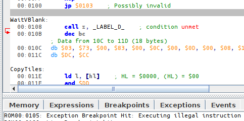

Okay, so, what happened?
As we can see from the screenshot, PC is at $0105. What is it doing there?
…Oh, EntryPoint is at $0103.
So the jp at $0100 went there, and started executing instructions (3E CE is the raw form of ld a, $CE), but then $ED does not encode any valid instruction, so the CPU locks up.
But why is EntryPoint there?
Well, as you may have figured out from the warnings RGBFIX printed, it overwrites the header area in the ROM.
However, RGBLINK is not aware of the header (because RGBLINK is not only used to generate ROMs!), so you must explicitly reserve space for the header area.
🥴
Forgetting to reserve this space, and having a piece of code or data ending up there then overwritten, is a common beginner mistake that can be quite puzzling. Fortunately, RGBFIX since version 0.5.1 warns when it detects this mistake, as shown above.
So, we prevent disaster like this:
SECTION "Header", ROM0[$100]

	jp EntryPoint

	ds $150 - @, 0 ; Make room for the header
The directive ds stands for “define space”, and allows filling a range of memory.
This specific line fills all bytes from $103 to $14F (inclusive) with the value $00.
Since different pieces of code and/or data cannot overlap, this ensures that the header’s memory range can safely be overwritten by RGBFIX, and that nothing else accidentally gets steamrolled instead.
It may not be obvious how this ds ends up filling that specific memory range.
The 3-byte jp covers memory addresses $100, $101, and $102.
(We start at $100 because that’s where the SECTION is hardcoded to be.)
When RGBASM processes the ds directive, @ (which is a special symbol that evaluates to “the current address”) thus has the value $103, so it fills $150 - $103 = $4D bytes with zeros, so $103, $104, …, $14E, $14F.
Bonus: the infinite loop
(This is not really linked to the header, but I need to explain it somewhere, and here is as good a place as any.)
You may also be wondering what the point of the infinite loop at the end of the code is for.
Done:
	jp Done
Well, simply enough, the CPU never stops executing instructions; so when our little Hello World is done and there is nothing left to do, we must still give the CPU some busy-work: so we make it do nothing, forever.
We cannot let the CPU just run off, as it would then start executing other parts of memory as code, possibly crashing. (See for yourself: remove or comment out these two lines, re-compile the ROM, and see what happens!)
Operations & flags
Alright, we know how to pass values around, but just copying numbers is no fun; we want to modify them!
The GB CPU does not provide every operation under the sun (for example, there is no multiplication instruction), but we can just program those ourselves with what we have. Let’s talk about some of the operations that it does have; I will be omitting some not used in the Hello World for now.
Arithmetic
The simplest arithmetic instructions the CPU supports are inc and dec, which INCrement and DECrement their operand, respectively.
(If you aren’t sure, “to increment” means “to add 1”, and “to decrement” means “to subtract 1”.)
So for example, the dec bc at line 32 of hello-world.asm simply subtracts 1 from bc.
Okay, cool!
Can we go a bit faster, though?
Sure we can, with add and sub!
These respectively ADD and SUBtract arbitrary values (either a constant, or a register).
Neither is used in the tutorial, but a sibling of sub’s is: have you noticed little cp over at line 17?
cp allows ComParing values.
It works the same as sub, but it discards the result instead of writing it back.
“Wait, so it does nothing?” you may ask; well, it does update the flags.
Flags
The time has come to talk about the special-purpose register (remember those?) f, for, well, flags.
The f register contains 4 bits, called “flags”, which are updated depending on an operation’s results.
These 4 flags are:
| Name | Description |
|---|---|
| Z | Zero flag |
| N | Addition/subtraction |
| H | Half-carry |
| C | Carry |
Yes, there is a flag called “C” and a register called “c”, and they are different, unrelated things. This makes the syntax a bit confusing at the beginning, but they are always used in different contexts, so it’s fine.
We will forget about N and H for now; let’s focus on Z and C. Z is the simplest flag: it gets set when an operation’s result is 0, and gets reset otherwise. C is set when an operation overflows or underflows.
What’s an overflow?
Let’s take the simple instruction add a, 42.
This simply adds 42 to the contents of register a, and writes the result back into a.
    ld a, 200
    add a, 42
At the end of this snippet, a equals 200 + 42 = 242, great!
But what if I write this instead?
    ld a, 220
    add a, 42
Well, one could think that a would be equal to 220 + 42 = 262, but that would be incorrect.
Remember, a is an 8-bit register, it can only store eight bits of information!
And if we were to write 262 in binary, we would get %100000110, which requires at least 9 bits…
So what happens?
Simply, that ninth bit is lost, and the value that we end up with is %00000110 = 6.
This is called an overflow: after adding, we get a value smaller than what we started with.
We can also do the opposite with sub, and—for example—subtract 42 from 6; as we know, for all X and Y, X + Y - Y = X, and we just saw that 220 + 42 = 6 (this is called modulo 256 arithmetic, by the way); so, 6 - 42 = (220 + 42) - 42 = 220.
This is called an underflow: after subtracting, we get a value greater than what we started with.
When an operation is performed, it sets the carry flag if an overflow or underflow occurred, and clears it otherwise. (We will see later that not all operations update the carry flag, though.)
Summary
- We can add and subtract numbers.
- The Z flag lets us know if the result was 0.
- However, registers can only store a limited range of integers.
- Going outside this range is called an overflow or underflow, for addition and subtraction respectively.
- The C flag lets us know if either occurred.
Comparison
Now, let’s talk more about how cp is used to compare numbers.
Here is a refresher: cp subtracts its operand from a and updates flags accordingly, but doesn’t write the result back.
We can use flags to check properties about the values being compared, and we will see in the next lesson how to use the flags.
The simplest interaction is with the Z flag.
If it’s set, we know that the subtraction yielded 0, i.e. a - operand == 0; therefore, a == operand!
If it’s not set, well, then we know that a != operand.
Okay, checking for equality is nice, but we may also want to perform comparisons. Fret not, for the carry flag is here to do just that! See, when performing a subtraction, the carry flag gets set when the result goes below 0—but that’s just a fancy way of saying “becomes negative”!
So, when the carry flag gets set, we know that a - operand < 0, therefore that a < operand..!
And, conversely, we know that if it’s not set, a >= operand.
Great!
Instruction summary
| Instruction | Mnemonic | Effect |
|---|---|---|
| Add | add | Adds values to a |
| Subtract | sub | Subtracts values from a |
| Compare | cp | Compares values with what’s contained in a |
Jumps
Once this lesson is done, we will be able to understand all of CopyTiles!
So far, all the code we have seen was linear: it executes top to bottom. But this doesn’t scale: sometimes, we need to perform certain actions depending on the result of others (“if the crêpes start sticking, grease the pan again”), and sometimes, we need to perform actions repeatedly (“If there is some batter left, repeat from step 5”).
Both of these imply reading the recipe non-linearly. In assembly, this is achieved using jumps.
The CPU has a special-purpose register called “PC”, for Program Counter. It contains the address of the instruction currently being executed1, like how you’d keep in mind the number of the recipe step you’re currently doing. PC increases automatically as the CPU reads instructions, so “by default” they are read sequentially; however, jump instructions allow writing a different value to PC, effectively jumping to another piece of the program. Hence the name.
Okay, so, let’s talk about those jump instructions, shall we? There are four of them:
| Instruction | Mnemonic | Effect |
|---|---|---|
| Jump | jp | Jump execution to a location |
| Jump Relative | jr | Jump to a location close by |
| Call | call | Call a subroutine |
| Return | ret | Return from a subroutine |
We will focus on jp for now.
jp, such as the one line 5, simply sets PC to its argument, jumping execution there.
In other words, after executing jp EntryPoint (line 5), the next instruction executed is the one below EntryPoint (line 11).
🤔
You may be wondering what is the point of that specific jp.
Don’t worry, we will see later why it’s required.
Conditional jumps
Now to the really interesting part. Let’s examine the loop responsible for copying tiles:
	; Copy the tile data
	ld de, Tiles
	ld hl, $9000
	ld bc, TilesEnd - Tiles
CopyTiles:
	ld a, [de]
	ld [hli], a
	inc de
	dec bc
	ld a, b
	or a, c
	jp nz, CopyTiles
Don’t worry if you don’t quite get all the following, as we’ll see it live in action in the next lesson. If you’re having trouble, try going to the next lesson, watch the code execute step by step; then, coming back here, it should make more sense.
First, we copy Tiles, the address of the first byte of tile data, into de.
Then, we set hl to $9000, which is the address where we will start copying the tile data to.
ld bc, TilesEnd - Tiles sets bc to the length of the tile data: TilesEnd is the address of the first byte after the tile data, so subtracting Tiles to that yields the length.
So, basically:
decontains the address where data will be copied from;hlcontains the address where data will be copied to;bccontains how many bytes we have to copy.
Then we arrive at the main loop.
We read one byte from the source (line 29), and write it to the destination (line 30).
We increment the destination (via the implicit inc hl done by ld [hli], a) and source pointers (line 31), so the following loop iteration processes the next byte.
Here’s the interesting part: since we’ve just copied one byte, that means we have one less to go, so we dec bc.
(We have seen dec two lessons ago; as a refresher, it simply decreases the value stored in bc by one.)
Since bc contains the amount of bytes that still need to be copied, it’s trivial to see that we should simply repeat the operation if bc != 0.
😓
dec usually updates flags, but unfortunately dec bc doesn’t, so we must check if bc reached 0 manually.
ld a, b and or a, c “bitwise OR” b and c together; it’s enough to know for now that it leaves 0 in a if and only if bc == 0.
And or updates the Z flag!
So, after line 34, the Z flag is set if and only if bc == 0, that is, if we should exit the loop.
And this is where conditional jumps come into the picture! See, it’s possible to conditionally “take” a jump depending on the state of the flags.
There are four “conditions”:
| Name | Mnemonic | Description |
|---|---|---|
| Zero | z | Z is set (last operation had a result of 0) |
| Non-zero | nz | Z is not set (last operation had a non-zero result) |
| Carry | c | C is set (last operation overflowed) |
| No carry | nc | C is not set (last operation did not overflow) |
Thus, jp nz, CopyTiles can be read as “if the Z flag is not set, then jump to CopyTiles”.
Since we’re jumping backwards, we will repeat the instructions again: we have just created a loop!
Okay, we’ve been talking about the code a lot, and we have seen it run, but we haven’t really seen how it runs. Let’s watch the magic unfold in slow-motion in the next lesson!
-
Not exactly; instructions may be several bytes long, and PC increments after reading each byte. Notably, this means that when an instruction finishes executing, PC is pointing to the following instruction. Still, it’s pretty much “where the CPU is currently reading from”, but it’s better to keep it simple and avoid mentioning instruction encoding for now. ↩
Tracing
Ever dreamed of being a wizard? Well, this won’t give you magical powers, but let’s see how emulators can be used to control time!
First, make sure to focus the debugger window.
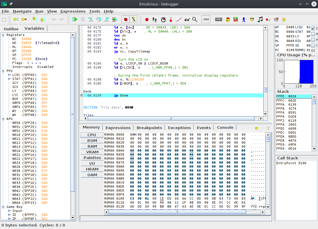
Let’s first explain the debugger’s layout:
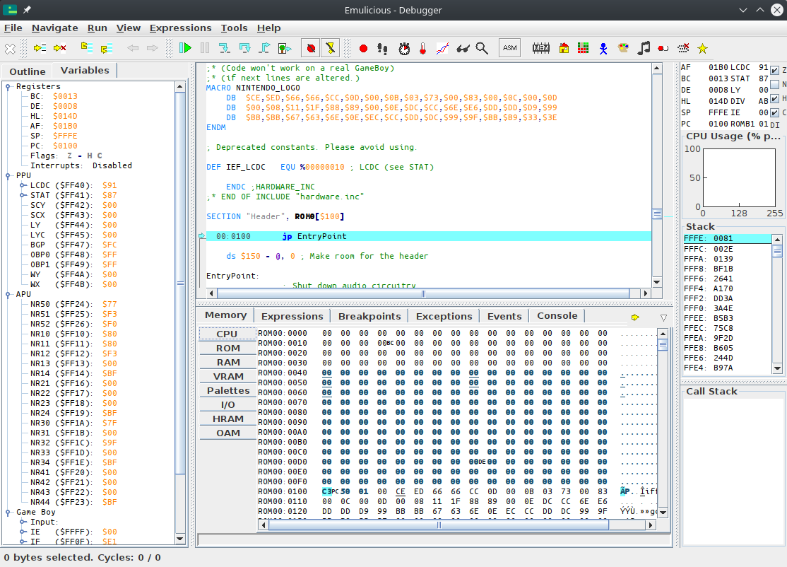 Top-left is the code viewer, bottom-left is the data viewer, top-right are some registers (as we saw in the registers lesson), and bottom-right is the stack viewer.
What’s the stack?
We will answer that question a bit later… in Part Ⅱ 😅
Top-left is the code viewer, bottom-left is the data viewer, top-right are some registers (as we saw in the registers lesson), and bottom-right is the stack viewer.
What’s the stack?
We will answer that question a bit later… in Part Ⅱ 😅
Setup
For now, let’s focus on the code viewer.
As Emulicious can load our source code, our code’s labels and comments are automatically shown in the debugger. As we have seen a couple of lessons ago, labels are merely a convenience provided by RGBASM, but they are not part of the ROM itself. In other emulators, it is very much inconvenient to debug without them, and so sym files (for “symbols”) have been developed. Let’s run RGBLINK to generate a sym file for our ROM:
rgblink -n hello-world.sym hello-world.o
‼️
The file names matter!
When looking for a ROM’s sym file, emulators take the ROM’s file name, strip the extension (here, .gb), replace it with .sym, and look for a file in the same directory with that name.
Stepping
When pausing execution, the debugger will automatically focus on the instruction the CPU is about to execute, as indicated by the line highlighted in blue.
ℹ️
The instruction highlighted in blue is always what the CPU is about to execute, not what it just executed. Keep this in mind.
If we want to watch execution from the beginning, we need to reset the emulator. Go into the emulator’s “File” menu, and select “Reset”, or press Ctrl+Backspace.
The blue line should automatically move to address $01001, and now we’re ready to trace! All the commands for that are in the “Run” menu.
- “Resume” simply unpauses the emulator.
- “Step Into” and “Step Over” advance the emulator by one instruction.
They only really differ on the
callinstruction, interrupts, and when encountering a conditional jump, neither of which we are using here, so we will use “Step Into”. - The other options are not relevant for now.
We will have to “Step Into” a bunch of times, so it’s a good idea to use the key shortcut.
If we press F5 once, the jp EntryPoint is executed.
And if we press it a few more times, can see the instructions being executed, one by one!
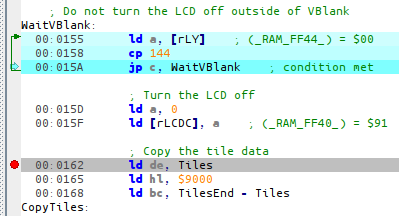
Now, you may notice the WaitVBlank loop runs a lot of times, but what we are interested in is the CopyTiles loop.
We can easily skip over it in several ways; this time, we will use a breakpoint.
We will place the breakpoint on the ld de, Tiles at 00:0162; either double-click on that line, or select it and press Ctrl+Shift+B.
Then you can resume execution by pressing F8. Whenever Emulicious is running, and the (emulated) CPU is about to execute an instruction a breakpoint was placed on, it automatically pauses.
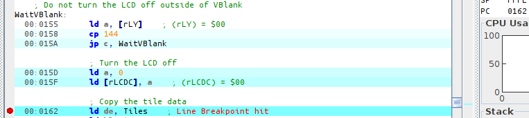
You can see where execution is being paused both from the green arrow and the value of PC.
If we trace the next three instructions, we can see the three arguments to the CopyTiles loop getting loaded into registers.

For fun, let’s watch the tiles as they’re being copied. For that, obviously, we will use the Memory Editor, and position it at the destination. As we can see from the image above, that would be $9000!
Click on “Memory” on the bottom window, then “VRAM”, and press Ctrl+G (for “Goto”).
Awesome, right?
What next?
Congrats, you have just learned how to use a debugger! We have only scratched the surface, though; we will use more of Emulicious’ tools to illustrate the next parts. Don’t worry, from here on, lessons will go with a lot more images—you’ve made it through the hardest part!
-
Why does execution start at $0100? That’s because it’s where the boot ROM hands off control to our game once it’s done. ↩
Tiles
💭
“Tiles” were called differently in documentation of yore. They were usually called “patterns” or “characters”, the latter giving birth to the “CHR” abbreviation which is sometimes used to refer to tiles.
For example, on the NES, tile data is usually provided by the cartridge in either CHR ROM or CHR RAM. The term “CHR” is typically not used on the Game Boy, though exchanges between communities cause terms to “leak”, so some refer to the area of VRAM where tiles are stored as “CHR RAM” or “CHR VRAM”, for example.
As with all such jargon whose meaning may depend on who you are talking to, I will stick to “tiles” across this entire tutorial for consistency, being what is the most standard in the GB dev community now.
Well, copying this data blindly is fine and dandy, but why exactly is the data “graphics”?
Ah, yes, pixels.
Let’s see about that!
Helpful hand
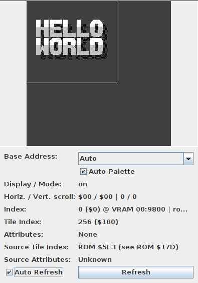
Now, figuring out the format with an explanation alone is going to be very confusing; but fortunately, Emulicious got us covered thanks to its Tile Viewer. You can open it either by selecting “Tools” then “Tile Viewer”, or by clicking on the grid of colored tiles in the debugger’s toolbar.
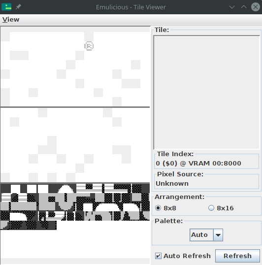
You can combine the various VRAM viewers by going to “View”, then “Combine Video Viewers”. We will come to the other viewers in due time. This one shows the tiles present in the Game Boy’s video memory (or “VRAM”).
🤔
I encourage you to experiment with the VRAM viewer, hover over things, tick and untick checkboxes, see by yourself what’s what. Any questions you might have will be answered in due time, don’t worry! And if what you’re seeing later on doesn’t match my screenshots, ensure that the checkboxes match mine.
Don’t mind the “®” icon in the top-left; we did not put it there ourselves, and we will see why it’s there later.
Short primer
You may have heard of tiles before, especially as they were really popular in 8-bit and 16-bit systems. That’s no coincidence: tiles are very useful. Instead of storing every on-screen pixel (144 × 160 pixels × 2 bits/pixel = 46080 bits = 5760 bytes, compared to the console’s 8192 bytes of VRAM), pixels are grouped into tiles, and then tiles are assembled in various ways to produce the final image.
In particular, tiles can be reused very easily and at basically no cost, saving a lot of memory! In addition, manipulating whole tiles at once is much cheaper than manipulating the individual pixels, so this spares processing time as well.
The concept of a “tile” is very general, but on the Game Boy, tiles are always 8 by 8 pixels. Often, hardware tiles are grouped to manipulate them as larger tiles (often 16×16); to avoid the confusion, those are referred to as meta-tiles.
“bpp”?
You may be wondering where that “2 bits/pixel” figure earlier came from… This is something called “bit depth”.
See, colors are not stored in the tiles themselves! Instead, it works like a coloring book: the tile itself contains 8 by 8 indices, not colors; you give the hardware a tile and a set of colors—a palette—and it colorizes them! (This is also why color swaps were very common back then: you could create enemy variations by storing tiny palettes instead of large different graphics.)
Anyway, as it is, Game Boy palettes are 4 colors large.1 This means that the indices into those palettes, stored in the tiles, can be represented in only two bits! This is called “2 bits per pixel”, noted “2bpp”.
With that in mind, we are ready to explain how these bytes turn into pixels!
Encoding
As I explained, each pixel takes up 2 bits. Since there are 8 bits in a byte, you might expect each byte to contain 4 pixels… and you would be neither entirely right, nor entirely wrong. See, each row of 8 pixels is stored in 2 bytes, but neither of these bytes contains the info for 4 pixels. (Think of it like a 10 € banknote torn in half: neither half is worth anything, but the full bill is worth, well, 10 €.)
For each pixel, the least significant bit of its index is stored in the first byte, and the most significant bit is stored in the second byte. Since each byte is a collection of one of the bits for each pixel, it’s called a bitplane.
The leftmost pixel is stored in the leftmost bit of both bytes, the pixel to its right in the second leftmost bit, and so on. The first pair of bytes stores the topmost row, the second byte the row below that, and so on.
Here is a more visual demonstration:
This encoding may seem a little weird at first, and it can be; it’s made to be more convenient for the hardware to decode, keeping the circuitry simple and low-power. It even makes a few cool tricks possible, as we will see (much) later!
You can read up more about the encoding in the Pan Docs and ShantyTown’s site.
In the next lesson, we shall see how colors are applied!
-
Other consoles can have varying bit depths; for example, the SNES has 2bpp, 4bpp, and 8bpp depending on the graphics mode and a few other parameters. ↩
Palettes
In the previous lesson, I briefly mentioned that colors are applied to tiles via palettes, but we haven’t talked much about those yet.
The black & white Game Boy has three palettes, one for the background called BGP (“BackGround Palette”), and two for the objects called OBP0 and OBP1 (“OBject Palette 0/1”).
If you are wondering what “objects” are, you will have to wait until Part Ⅱ to find out; for now, let’s focus on the background.
🌈
The Game Boy Color introduced, obviously, colors, and this was mainly done by reworking the way palettes are handled. We will not talk about Game Boy Color features in Part Ⅰ for the sake of simplicity, but we will do so in later parts.
If you chose to combine the video viewers in the previous chapter, the palette viewer should show up on the bottom right of the video viewer.
Otherwise, please select Emulicious’ “Tools” tab, then select Palette Viewer.
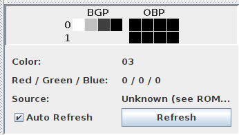
We will be taking a look at the “BGP” line. As I explained before, tiles store “color indices” for each pixel, which are used to index into the palette. Color number 01 is the leftmost in that line, and number 3 is the rightmost.
So, in our case, color number 0 is “white”, color number 1 is “light gray”, number 2 is “dark gray”, and number 3 “black”. I put air quotes because “black” isn’t true black, and “white” isn’t true white. Further, note that the original Game Boy had shades of green, but the later Game Boy Pocket’s screen produced shades of gray instead. And, even better, the Game Boy Color will automatically colorize games that lack Game Boy Color support!

All this to say, one shouldn’t expect specific colors out of a Game Boy game2, just four more or less bright colors.
Getting our hands dirty
Well, so far in this tutorial, besides running the Hello World, we have been pretty passive, watching it unfold. What do you say we start prodding the ROM a bit?
In Emulicious’ debugger, select the “Variables” tab on the left to show the IO registers.
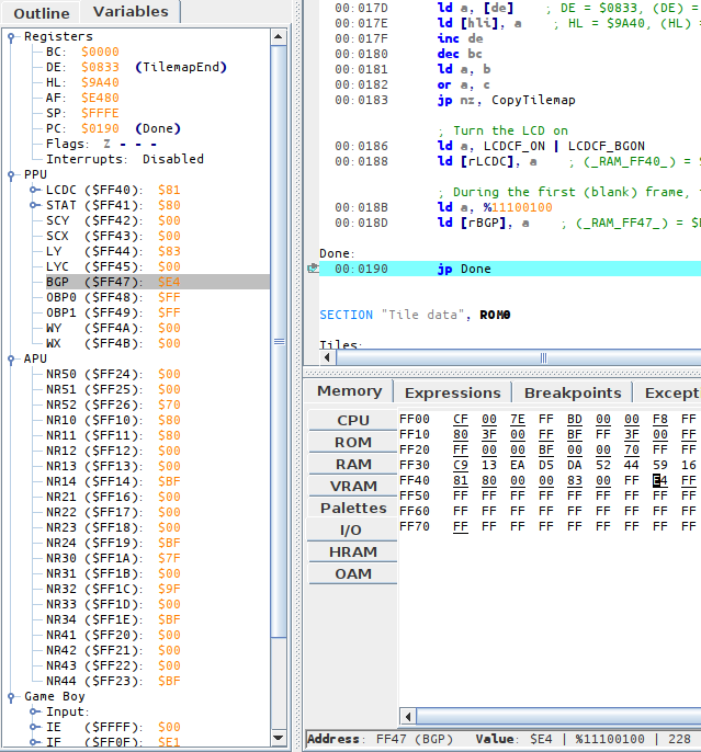
While the VRAM viewer offers a visual representation of the palette, the IO map shows the nitty-gritty: how it’s encoded. The IO map also lets us modify BGP easily; but to do so, we need to understand how values we write are turned into colors.
Encoding
Fortunately, the encoding is very simple. I will explain it, and at the same time, give an example with the palette we have at hand, $E4.
Take the byte, break its 8 bits into 4 groups of 2.
[BGP] = $E4
$E4 = %11100100 (refresh your memory in the "Binary and hexadecimal" lesson if needed!)
That gets broken down into %11, %10, %01, %00
Color number 0 is the rightmost “group”, color number 3 is the leftmost one. Simple! And this matches what the VRAM viewer is showing us: color number 0, the rightmost, is the brightest (%00), up to color number 3, the leftmost and the darkest (%11).
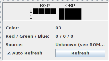
Lights out
For fun, let’s make the screen completely black.
We can easily do this by setting all colors in the palette to black (%11).
This would be %11 %11 %11 %11 = $FF.
In the “Variables” tab in the debugger, click on the byte to the right of BGP, erase the “E4”, type “FF”, and hit Enter. BGP immediately updates, turning the screen black!
What if we wanted to take the original palette, but invert it? %11 would become %00, %01 would become %10, %10 would become %01, and %00 would become %11. We would get thus:
%11_10_01_00
 ↓  ↓  ↓  ↓
%00_01_10_11
(I’m not giving the value in hexadecimal, use this as an opportunity to exercise your bin-to-hex conversions!)

If you go to the Tile Viewer and change “Palette” to “Gray”, you will notice that the tile data stays the same regardless of how the palette is modified! This is an advantage of using palettes: fading the screen in and out is very cheap, just modifying a single byte, instead of having to update every single on-screen pixel.
Got all that? Then let’s take a look at the last missing puzzle piece in the Hello World’s rendering process, the tilemap!
-
Numbering often starts at 0 when working with computers. We will understand why later, but for now, please bear with it! ↩
-
Well, it is possible to detect these different models and account for them, but this would require taking plenty of corner cases into consideration, so it’s probably not worth the effort. ↩
Tilemap
🧐
Some spell them “tile map”, some “tilemap”.
I will be using the latter by preference, but I also stay consistent with it in the code (Tilemap and not TileMap), as well as later when we will talk about attribute maps (“attrmap” and Attrmap instead of AttrMap).
We are almost there. We have seen how graphics on the Game Boy are composed of 8×8 “tiles”, and we have seen how color is added into the mix.
But we have not seen yet how those tiles are arranged into a final picture!
Tiles are basically a grid of pixels; well, the tilemaps are basically a grid of tiles! To allow for cheap reuse, tiles aren’t stored in the tilemap directly; instead, tiles are referred to by an ID, which you can see in Emulicious’ Tile Viewer.
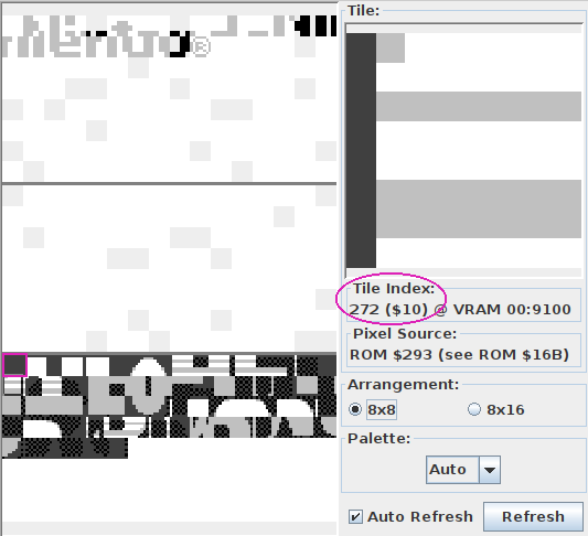
Now, of course, tile IDs are numbers, like everything that computers deal with. IDs are stored in bytes, so there are 256 possible tile IDs. However, the astute reader will have noticed that there are 384 tiles in total1! By virtue of the pigeonhole principle, this means that some IDs refer to several tiles at the same time.
Indeed, Emulicious reports that the first 128 tiles have the same IDs as the last 128. There exists a mechanism to select whether IDs 0–127 reference the first or last 128 tiles, but for simplicity’s sake, we will overlook this for now, so please ignore the first (topmost) 128 tiles for the time being.
Now, please turn your attention to Emulicious’ Tilemap Viewer, pictured below.
You may notice that the image shown is larger than what is displayed on-screen. Only part of the tilemap, outlined by a thicker border in the Tilemap Viewer, is displayed on-screen at a given time. We will explain this in more detail in Part Ⅱ.
Here we will be able to see the power of tile reuse in full force. As a convenience and a refresher, here are the tiles our Hello World loads into VRAM:
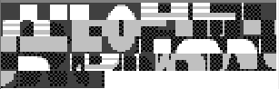
You can see that we only loaded a single “blank” tile ($00, the first aka. top-left one), but it can be repeated to cover the whole background at no extra cost!
Repetition can be more subtle: for example, tile $01 is used for the top-left corner of the H, E, L, L, and W (red lines below)! The R, L, and D also both share their top-left tile ($2D, blue lines below); and so on. You can confirm this by hovering over tiles in the BG map tab, which shows the ID of the tile at that position.

All in all, we can surmise that displaying graphics on the Game Boy consists of loading “patterns” (the tiles), and then telling the console which tile to display for each given location.
-
The even more astute (astuter?) reader will have noticed that 384 = 3 × 128. Thus, tiles are often conceptually grouped into three “blocks” of 128 tiles each, which Emulicious shows as separated by thicker horizontal lines. ↩
Wrapping up
Congrats! You have made it through the first part of this tutorial. By this point, you have a basic enough understanding of the console that you know how to display a picture. And hey, that doesn’t sound like much, but consider everything you have seen so far—there is a lot that goes into it!
🥳
Honestly, congrats on coming this far—many people have given up earlier than this. So you can give yourself a pat on the back, you honestly deserve it! Now may also be a good time to take a break if you are reading all this in a single trait. I encourage you to give it a little time to sink in, and maybe go back to the lessons you struggled on the most. Maybe a second read can help.
And yes, you could simply have let a library handle all that. However, the details always leak through eventually, so knowing about them is helpful, if only for debugging.
Plus, understanding what’s really going on under the hood makes you a better programmer, even if you don’t end up using ASM in the long run. Amusingly, even modern systems work similarly to older ones in unexpected places, so some things you just learned will carry over! Trust me, everything you have learned and will learn is worth it! ✊
That said, right now, you may have a lot of questions.
- Why do we turn off the LCD?
- We know how to make a static picture, but how to we add motion into the mix?
- Also, how do I get input from the player?
- The code mentions shutting down audio, but how do I play some of those famed beeps and bloops?
- Writing graphics in that way sound tedious, is there no other way?
- Actually, wait, how do we make a game out of all this??
… All of that answered, and more, in Part Ⅱ! 👀
Getting started
In this lesson, we will start a new project from scratch. We will make a Breakout / Arkanoid clone, which we’ll call “Unbricked”! (Though you are free to give it any other name you like, as it will be your project.)
Open a terminal and make a new directory (mkdir unbricked), and then enter it (cd unbricked), just like you did for “Hello, world!”.
Start by creating a file called main.asm, and include hardware.inc in your code.
INCLUDE "hardware.inc"
You may be wondering what purpose hardware.inc serves.
Well, the code we write only really affects the CPU, but does not do anything with the rest of the console (not directly, anyway).
To interact with other components (like the graphics system, say), Memory-Mapped I/O (MMIO) is used: basically, memory in a certain range (addresses $FF00–FF7F) does special things when accessed.
These bytes of memory being interfaces to the hardware, they are called hardware registers (not to be mistaken with the CPU registers).
For example, the “PPU status” register is located at address $FF41.
Reading from that address reports various bits of info regarding the graphics system, and writing to it allows changing some parameters.
But, having to remember all the numbers (non-exhaustive list) would be very tedious—and this is where hardware.inc comes into play!
hardware.inc defines one constant for each of these registers (for example, rSTAT for the aforementioned “PPU status” register), plus some additional constants for values read from or written to these registers.
Don’t worry if this flew over your head, we’ll see an example below with rLCDC and LCDCF_ON.
By the way, the r stands for “register”, and the F in LCDCF stands for “flag”.
Next, make room for the header. Remember from Part Ⅰ that the header is where some information that the Game Boy relies on is stored, so you don’t want to accidentally leave it out.
SECTION "Header", ROM0[$100]

	jp EntryPoint

	ds $150 - @, 0 ; Make room for the header
The header jumps to EntryPoint, so let’s write that now:
EntryPoint:
	; Do not turn the LCD off outside of VBlank
WaitVBlank:
	ld a, [rLY]
	cp 144
	jp c, WaitVBlank

	; Turn the LCD off
	ld a, 0
	ld [rLCDC], a
The next few lines wait until “VBlank”, which is the only time you can safely turn off the screen (doing so at the wrong time could damage a real Game Boy, so this is very crucial). We’ll explain what VBlank is and talk about it more later in the tutorial.
Turning off the screen is important because loading new tiles while the screen is on is tricky—we’ll touch on how to do that in Part 3.
Speaking of tiles, we’re going to load some into VRAM next, using the following code:
	; Copy the tile data
	ld de, Tiles
	ld hl, $9000
	ld bc, TilesEnd - Tiles
CopyTiles:
	ld a, [de]
	ld [hli], a
	inc de
	dec bc
	ld a, b
	or a, c
	jp nz, CopyTiles
This loop might be reminiscent of part Ⅰ.
It copies starting at Tiles to $9000 onwards, which is the part of VRAM where our tiles are going to be stored.
Recall that $9000 is where the data of background tile $00 lies, and the data of subsequent tiles follows right after.
To get the number of bytes to copy, we will do just like in Part Ⅰ: using another label at the end, called TilesEnd, the difference between it (= the address after the last byte of tile data) and Tiles (= the address of the first byte) will be exactly that length.
That said, we haven’t written Tiles nor any of the related data yet.
We’ll get to that later!
Almost done now—next, write another loop, this time for copying the tilemap.
	; Copy the tilemap
	ld de, Tilemap
	ld hl, $9800
	ld bc, TilemapEnd - Tilemap
CopyTilemap:
	ld a, [de]
	ld [hli], a
	inc de
	dec bc
	ld a, b
	or a, c
	jp nz, CopyTilemap
Note that while this loop’s body is exactly the same as CopyTiles’s, the 3 values loaded into de, hl, and bc are different.
These determine the source, destination, and size of the copy, respectively.
"Don't Repeat Yourself"
If you think that this is super redundant, you are not wrong, and we will see later how to write actual, reusable functions. But there is more to them than meets the eye, so we will start tackling them much later.
Finally, let’s turn the screen back on, and set a background palette.
Rather than writing the non-descript number %10000001 (or $81 or 129, to taste), we make use of two constants graciously provided by hardware.inc: LCDCF_ON and LCDCF_BGON.
When written to rLCDC, the former causes the PPU and screen to turn back on, and the latter enables the background to be drawn.
(There are other elements that could be drawn, but we are not enabling them yet.)
Combining these constants must be done using |, the binary “or” operator; we’ll see why later.
	; Turn the LCD on
	ld a, LCDCF_ON | LCDCF_BGON
	ld [rLCDC], a

	; During the first (blank) frame, initialize display registers
	ld a, %11100100
	ld [rBGP], a

Done:
	jp Done
There’s one last thing we need before we can build the ROM, and that’s the graphics. We will draw the following screen:
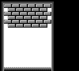
In hello-world.asm, tile data had been written out by hand in hexadecimal; this was to let you see how the sausage is made at the lowest level, but boy is it impractical to write!
This time, we will employ a more friendly way, which will let us write each row of pixels more easily.
For each row of pixels, instead of writing the bitplanes directly, we will use a backtick (```) followed by 8 characters.
Each character defines a single pixel, intuitively from left to right; it must be one of 0, 1, 2, and 3, representing the corresponding color index in the palette.
If the character selection isn’t to your liking, you can use RGBASM’s -g option or OPT g to pick others.
For example, rgbasm -g '.xXO' (...) or OPT g.xXO would swap the four characters to ., x, X, and O respectively.
For example:
dw `01230123 ; This is equivalent to `db $55,$33`
You may have noticed that we are using dw instead of db; the difference between these two will be explained later.
We already have tiles made for this project, so you can copy this premade file, and paste it at the end of your code.
Then copy the tilemap from this file, and paste it after the TilesEnd label.
You can build the ROM now, by running the following commands in your terminal:
rgbasm -o main.o main.asm
rgblink -o unbricked.gb main.o
rgbfix -v -p 0xFF unbricked.gb
If you run this in your emulator, you should see the following:
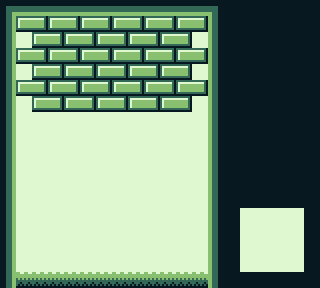
That white square seems to be missing! You may have noticed this comment earlier, somewhere in the tile data:
	dw `22322232
	dw `23232323
	dw `33333333
	; Paste your logo here:

TilesEnd:
The logo tiles were left intentionally blank so that you can choose your own. You can use one of the following pre-made logos, or try coming up with your own!


Add your chosen logo’s data (click one of the “Source” links above) after the comment, build the game again, and you should see your logo of choice in the bottom-right!
Objects
The background is very useful when the whole screen should move at once, but this is not ideal for everything. For example, a cursor in a menu, NPCs and the player in a RPG, bullets in a shmup, or balls in an Arkanoid clone… all need to move independently of the background. Thankfully, the Game Boy has a feature that’s perfect for these! In this lesson, we will talk about objects (sometimes called “OBJ”).
The above description may have made you think of the term “sprite” instead of “object”. The term “sprite” has a lot of meanings depending on context, so, to avoid confusion, this tutorial tries to use specific alternatives instead, such as object, metasprite, actor, etc.
Each object allows drawing one or two tiles (so 8×8 or 8×16 pixels, respectively) at any on-screen position—unlike the background, where all the tiles are drawn in a grid. Therefore, an object consists of its on-screen position, a tile ID (like with the tilemap), and some extra properties called “attributes”. These extra properties allow, for example, to display the tile flipped. We’ll see more about them later.
Just like how the tilemap is stored in VRAM, objects live in a region of memory called OAM, meaning Object Attribute Memory. Recall from above that an object consists of:
- Its on-screen position
- A tile ID
- The “attributes”
These are stored in 4 bytes: one for the Y coordinate, one for the X coordinate, one for the tile ID, and one for the attributes. OAM is 160 bytes long, and since 160 ∕ 4 = 40, the Game Boy stores a total of 40 objects at any given time.
There is a catch, though: an object’s Y and X coordinate bytes in OAM do not store its on-screen position! Instead, the on-screen X position is the stored X position minus 8, and the on-screen Y position is the stored Y position minus 16. To stop displaying an object, we can simply put it off-screen, e.g. by setting its Y position to 0.
These offsets are not arbitrary! Consider an object’s maximum size: 8 by 16 pixels. These offsets allow objects to be clipped by the left and top edges of the screen. The NES, for example, lacks such offsets, so you will notice that objects always disappear after hitting the left or top edge of the screen.
Let’s discover objects by experimenting with them!
First off, when the Game Boy is powered on, OAM is filled with a bunch of semi-random values, which may cover the screen with some random garbage.
Let’s fix that by first clearing OAM before enabling objects for the first time.
Let’s add the following just after the CopyTilemap loop:
	ld a, 0
	ld b, 160
	ld hl, _OAMRAM
ClearOam:
	ld [hli], a
	dec b
	jp nz, ClearOam
This is a good time to do that, since just like VRAM, the screen must be off to safely access OAM.
Once OAM is clear, we can draw an object by writing its properties.
	ld hl, _OAMRAM
	ld a, 128 + 16
	ld [hli], a
	ld a, 16 + 8
	ld [hli], a
	ld a, 0
	ld [hli], a
	ld [hli], a
Remember that each object in OAM is 4 bytes, in the order Y, X, Tile ID, Attributes. So, the object’s top-left pixel lies 128 pixels from the top of the screen, and 16 from its left. The tile ID and attributes are both set to 0.
You may remember from the previous lesson that we’re already using tile ID 0, as it’s the start of our background’s graphics. However, by default objects and backgrounds use a different set of tiles, at least for the first 128 IDs. Tiles with IDs 128–255 are shared by both, which is useful if you have a tile that’s used both on the background and by an object.
If you go to “Tools”, then “Tile Viewer” in Emulicious’ debugger, you should see three distinct sections.

Because we need to load this to a different area, we’ll use the address $8000 and load a graphic for our game’s paddle.
Let’s do so right after CopyTilemap:
	; Copy the paddle tile
	ld de, Paddle
	ld hl, $8000
	ld bc, PaddleEnd - Paddle
CopyPaddle:
	ld a, [de]
	ld [hli], a
	inc de
	dec bc
	ld a, b
	or a, c
	jp nz, CopyPaddle
And don’t forget to add Paddle to the bottom of your code.
Paddle:
	dw `13333331
	dw `30000003
	dw `13333331
	dw `00000000
	dw `00000000
	dw `00000000
	dw `00000000
	dw `00000000
PaddleEnd:
Finally, let’s enable objects and see the result.
Objects must be enabled by the familiar rLCDC register, otherwise they just don’t show up.
(This is why we didn’t have to clear OAM in the previous lessons.)
We will also need to initialize one of the object palettes, rOBP0.
There are actually two object palettes, but we’re only going to use one.
	; Turn the LCD on
	ld a, LCDCF_ON | LCDCF_BGON | LCDCF_OBJON
	ld [rLCDC], a

	; During the first (blank) frame, initialize display registers
	ld a, %11100100
	ld [rBGP], a
	ld a, %11100100
	ld [rOBP0], a
Movement
Now that you have an object on the screen, let’s move it around.
Previously, the Done loop did nothing; let’s rename it to Main and use it to move our object.
We’re going to wait for VBlank before changing OAM, just like we did before turning off the screen.
Main:
    ; Wait until it's *not* VBlank
    ld a, [rLY]
    cp 144
    jp nc, Main
WaitVBlank2:
	ld a, [rLY]
	cp 144
	jp c, WaitVBlank2

	; Move the paddle one pixel to the right.
	ld a, [_OAMRAM + 1]
	inc a
	ld [_OAMRAM + 1], a
	jp Main
🤨
Here, we are accessing OAM without turning the LCD off, but it’s still safe. Explaining why requires a more thorough explanation of the Game Boy’s rendering, so let’s ignore it for now.
Now you should see the paddle moving… very quickly. Because it moves by a pixel every frame, it’s going at a speed of 60 pixels per second! To slow this down, we’ll use a variable.
So far, we have only worked with the CPU registers, but you can create global variables too!
To do this, let’s create another section, but putting it in WRAM0 instead of ROM0.
Unlike ROM (“Read-Only Memory”), RAM (“Random-Access Memory”) can be written to; thus, WRAM, or Work RAM, is where we can store our game’s variables.
Add this to the bottom of your file:
SECTION "Counter", WRAM0
wFrameCounter: db
Now we’ll use the wFrameCounter variable to count how many frames have passed since we last moved the paddle.
Every 15th frame, we’ll move the paddle by one pixel, slowing it down to 4 pixels per second.
Don’t forget that RAM is filled with garbage values when the Game Boy starts, so we need to initialize our variables before first using them.
	; Initialize global variables
	ld a, 0
	ld [wFrameCounter], a

Main:
	ld a, [rLY]
	cp 144
	jp nc, Main
WaitVBlank2:
	ld a, [rLY]
	cp 144
	jp c, WaitVBlank2

	ld a, [wFrameCounter]
	inc a
	ld [wFrameCounter], a
	cp a, 15 ; Every 15 frames (a quarter of a second), run the following code
	jp nz, Main

	; Reset the frame counter back to 0
	ld a, 0
	ld [wFrameCounter], a

	; Move the paddle one pixel to the right.
	ld a, [_OAMRAM + 1]
	inc a
	ld [_OAMRAM + 1], a
	jp Main
Alright! Up next is us taking control of that little paddle.
Functions
So far, we have only written a single “flow” of code, but we can already spot some snippets that look redundant. Let’s use functions to “factor out” code!
For example, in three places, we are copying chunks of memory around.
Let’s write a function below the jp Main, and let’s call it Memcpy, like the similar C function:
; Copy bytes from one area to another.
; @param de: Source
; @param hl: Destination
; @param bc: Length
Memcopy:
	ld a, [de]
	ld [hli], a
	inc de
	dec bc
	ld a, b
	or a, c
	jp nz, Memcopy
	ret
The new ret instruction should immediately catch our eye.
It is, unsurprisingly, what makes execution return to where the function was called from.
Importantly, many languages have a definite “end” to a function: in C or Rust, that’s the closing brace }; in Pascal or Lua, the keyword end, and so on; the function implicitly returns when execution reaches its end.
However, this is not the case in assembly, so you must remember to add a ret instruction at the end of the function to return from it!
Otherwise, the results are unpredictable.
Notice the comment above the function, explaining which registers it takes as input. This comment is important so that you know how to interface with the function; assembly has no formal parameters, so comments explaining them are even more important than with other languages. We’ll see more of those as we progress.
There are three places in the initialization code where we can use the Memcpy function.
Find each of these copy loops and replace them with a call to Memcpy; for this, we use the call instruction.
The registers serve as parameters to the function, so we’ll leave them as-is.
| Before | After |
|---|---|
|
|
|
|
|
|
In the next chapter, we’ll write another function, this time to read player input.
Input
We have the building blocks of a game here, but we’re still lacking player input. A game that plays itself isn’t very much fun, so let’s fix that.
Paste this code below your Main loop.
Like Memcpy, this is a function that can be reused from different places, using the call instruction.
UpdateKeys:
; Poll half the controller
ld a, P1F_GET_BTN
call .onenibble
ld b, a ; B7-4 = 1; B3-0 = unpressed buttons
; Poll the other half
ld a, P1F_GET_DPAD
call .onenibble
swap a ; A7-4 = unpressed directions; A3-0 = 1
xor a, b ; A = pressed buttons + directions
ld b, a ; B = pressed buttons + directions
; And release the controller
ld a, P1F_GET_NONE
ldh [rP1], a
; Combine with previous wCurKeys to make wNewKeys
ld a, [wCurKeys]
xor a, b ; A = keys that changed state
and a, b ; A = keys that changed to pressed
ld [wNewKeys], a
ld a, b
ld [wCurKeys], a
ret
.onenibble
ldh [rP1], a ; switch the key matrix
call .knownret ; burn 10 cycles calling a known ret
ldh a, [rP1] ; ignore value while waiting for the key matrix to settle
ldh a, [rP1]
ldh a, [rP1] ; this read counts
or a, $F0 ; A7-4 = 1; A3-0 = unpressed keys
.knownret
ret
Unfortunately, reading input on the Game Boy is fairly involved (as you can see!), and it would be quite difficult to explain what this function does right now. So, I ask that you make an exception, and trust me that this function does read input. Alright? Good!
Now that we know how to use functions, let’s call the UpdateKeys function in our main loop to read user input.
UpdateKeys writes the held buttons to a location in memory that we called wCurKeys, which we can read from after the function returns.
Because of this, we only need to call UpdateKeys once per frame.
This is important, because not only is it faster to reload the inputs that we’ve already processed, but it also means that we will always act on the same inputs, even if the player presses or releases a button mid-frame.
First, let’s set aside some room for the two variables that UpdateKeys will use; paste this at the end of the main.asm:
SECTION "Input Variables", WRAM0
wCurKeys: db
wNewKeys: db
Each variable must reside in RAM, and not ROM, because ROM is “Read-Only” (so you can’t modify it).
Additionally, each variable only needs to be one byte large, so we use db (“Define Byte”) to reserve one byte of RAM for each.
Before we read these variables we will also want to initialize them.
We can do that below our initialization of wFrameCounter.
; Initialize global variables
ld a, 0
ld [wFrameCounter], a
ld [wCurKeys], a
ld [wNewKeys], a
We’re going to use the and opcode, which we can use to set the zero flag (z) to the value of the bit.
We can use this along with the PADF constants in hardware.inc to read a particular key.
Main:
ld a, [rLY]
cp 144
jp nc, Main
WaitVBlank2:
ld a, [rLY]
cp 144
jp c, WaitVBlank2
; Check the current keys every frame and move left or right.
call UpdateKeys
; First, check if the left button is pressed.
CheckLeft:
ld a, [wCurKeys]
and a, PADF_LEFT
jp z, CheckRight
Left:
; Move the paddle one pixel to the left.
ld a, [_OAMRAM + 1]
dec a
; If we've already hit the edge of the playfield, don't move.
cp a, 15
jp z, Main
ld [_OAMRAM + 1], a
jp Main
; Then check the right button.
CheckRight:
ld a, [wCurKeys]
and a, PADF_RIGHT
jp z, Main
Right:
; Move the paddle one pixel to the right.
ld a, [_OAMRAM + 1]
inc a
; If we've already hit the edge of the playfield, don't move.
cp a, 105
jp z, Main
ld [_OAMRAM + 1], a
jp Main
Now, if you compile the project, you should be able to move the paddle left and right using the d-pad!! Hooray, we have the beginnings of a game!
Collision
Being able to move around is great, but there’s still one object we need for this game: a ball! Just like with the paddle, the first step is to create a tile for the ball and load it into VRAM.
Graphics
Add this to the bottom of your file along with the other graphics:
Ball:
dw `00033000
dw `00322300
dw `03222230
dw `03222230
dw `00322300
dw `00033000
dw `00000000
dw `00000000
BallEnd:
Now copy it to VRAM somewhere in your initialization code, e.g. after copying the paddle’s tile.
; Copy the ball tile
ld de, Ball
ld hl, $8010
ld bc, BallEnd - Ball
call Memcopy
In addition, we need to initialize an entry in OAM, following the code that initializes the paddle.
; Initialize the paddle sprite in OAM
ld hl, _OAMRAM
ld a, 128 + 16
ld [hli], a
ld a, 16 + 8
ld [hli], a
ld a, 0
ld [hli], a
ld [hli], a
; Now initialize the ball sprite
ld a, 100 + 16
ld [hli], a
ld a, 32 + 8
ld [hli], a
ld a, 1
ld [hli], a
ld a, 0
ld [hli], a
As the ball bounces around the screen its momentum will change, sending it in different directions.
Let’s create two new variables to track the ball’s momentum in each axis: wBallMomentumX and wBallMomentumY.
SECTION "Counter", WRAM0
wFrameCounter: db
SECTION "Input Variables", WRAM0
wCurKeys: db
wNewKeys: db
SECTION "Ball Data", WRAM0
wBallMomentumX: db
wBallMomentumY: db
We will need to initialize these before entering the game loop, so let’s do so right after we write the ball to OAM. By setting the X momentum to 1, and the Y momentum to -1, the ball will start out by going up and to the right.
; Now initialize the ball sprite
ld a, 100 + 16
ld [hli], a
ld a, 32 + 8
ld [hli], a
ld a, 1
ld [hli], a
ld a, 0
ld [hli], a
; The ball starts out going up and to the right
ld a, 1
ld [wBallMomentumX], a
ld a, -1
ld [wBallMomentumY], a
Prep work
Now for the fun part!
Add a bit of code at the beginning of your main loop that adds the momentum to the OAM positions.
Notice that since this is the second OAM entry, we use + 4 for Y and + 5 for X.
This can get pretty confusing, but luckily we only have two objects to keep track of.
In the future, we’ll go over a much easier way to use OAM.
Main:
ld a, [rLY]
cp 144
jp nc, Main
WaitVBlank2:
ld a, [rLY]
cp 144
jp c, WaitVBlank2
; Add the ball's momentum to its position in OAM.
ld a, [wBallMomentumX]
ld b, a
ld a, [_OAMRAM + 5]
add a, b
ld [_OAMRAM + 5], a
ld a, [wBallMomentumY]
ld b, a
ld a, [_OAMRAM + 4]
add a, b
ld [_OAMRAM + 4], a
You might want to compile your game again to see what this does. If you do, you should see the ball moving around, but it will just go through the walls and then fly offscreen.
To fix this, we need to add collision detection so that the ball can bounce around. We’ll need to repeat the collision check a few times, so we’re going to make use of two functions to do this.
Please do not get stuck on the details of this next function, as it uses some techniques and instructions we haven’t discussed yet. The basic idea is that it converts the position of the sprite to a location on the tilemap. This way, we can check which tile our ball is touching so that we know when to bounce!
; Convert a pixel position to a tilemap address
; hl = $9800 + X + Y * 32
; @param b: X
; @param c: Y
; @return hl: tile address
GetTileByPixel:
; First, we need to divide by 8 to convert a pixel position to a tile position.
; After this we want to multiply the Y position by 32.
; These operations effectively cancel out so we only need to mask the Y value.
ld a, c
and a, %11111000
ld l, a
ld h, 0
; Now we have the position * 8 in hl
add hl, hl ; position * 16
add hl, hl ; position * 32
; Convert the X position to an offset.
ld a, b
srl a ; a / 2
srl a ; a / 4
srl a ; a / 8
; Add the two offsets together.
add a, l
ld l, a
adc a, h
sub a, l
ld h, a
; Add the offset to the tilemap's base address, and we are done!
ld bc, $9800
add hl, bc
ret
The next function is called IsWallTile, and it’s going to contain a list of tiles which the ball can bounce off of.
; @param a: tile ID
; @return z: set if a is a wall.
IsWallTile:
cp a, $00
ret z
cp a, $01
ret z
cp a, $02
ret z
cp a, $04
ret z
cp a, $05
ret z
cp a, $06
ret z
cp a, $07
ret
This function might look a bit strange at first.
Instead of returning its result in a register, like a, it returns it in a flag: Z!
If at any point a tile matches, the function has found a wall and exits with Z set.
If the target tile ID (in a) matches one of the wall tile IDs, the corresponding cp will leave Z set; if so, we return immediately (via ret z), with Z set.
But if we reach the last comparison and it still doesn’t set Z, then we will know that we haven’t hit a wall and don’t need to bounce.
Putting it together
Time to use these new functions to add collision detection! Add the following after the code that updates the ball’s position:
BounceOnTop:
; Remember to offset the OAM position!
; (8, 16) in OAM coordinates is (0, 0) on the screen.
ld a, [_OAMRAM + 4]
sub a, 16 + 1
ld c, a
ld a, [_OAMRAM + 5]
sub a, 8
ld b, a
call GetTileByPixel ; Returns tile address in hl
ld a, [hl]
call IsWallTile
jp nz, BounceOnRight
ld a, 1
ld [wBallMomentumY], a
You’ll see that when we load the sprite’s positions, we subtract from them before calling GetTileByPixel.
You might remember from the last chapter that OAM positions are slightly offset; that is, (0, 0) in OAM is actually completely offscreen.
These sub instructions undo this offset.
However, there’s a bit more to this: you might have noticed that we subtracted an extra pixel from the Y position. That’s because (as the label suggests), this code is checking for a tile above the ball. We actually need to check all four sides of the ball so we know how to change the momentum according to which side collided, so… let’s add the rest!
BounceOnRight:
ld a, [_OAMRAM + 4]
sub a, 16
ld c, a
ld a, [_OAMRAM + 5]
sub a, 8 - 1
ld b, a
call GetTileByPixel
ld a, [hl]
call IsWallTile
jp nz, BounceOnLeft
ld a, -1
ld [wBallMomentumX], a
BounceOnLeft:
ld a, [_OAMRAM + 4]
sub a, 16
ld c, a
ld a, [_OAMRAM + 5]
sub a, 8 + 1
ld b, a
call GetTileByPixel
ld a, [hl]
call IsWallTile
jp nz, BounceOnBottom
ld a, 1
ld [wBallMomentumX], a
BounceOnBottom:
ld a, [_OAMRAM + 4]
sub a, 16 - 1
ld c, a
ld a, [_OAMRAM + 5]
sub a, 8
ld b, a
call GetTileByPixel
ld a, [hl]
call IsWallTile
jp nz, BounceDone
ld a, -1
ld [wBallMomentumY], a
BounceDone:
That was a lot, but now the ball bounces around your screen! There’s just one last thing to do before this chapter is over, and thats ball-to-paddle collision.
Paddle bounce
Unlike with the tilemap, there’s no position conversions to do here, just straight comparisons.
However, for these, we will need the carry flag.
The carry flag is notated as C, like how the zero flag is notated as Z, but don’t confuse it with the c register!
A refresher on comparisons
Just like Z, you can use the carry flag to jump conditionally.
However, while Z is used to check if two numbers are equal, C can be used to check if a number is greater than or smaller than another one.
For example, cp a, b sets C if a < b, and clears it if a >= b.
(If you want to check a <= b or a > b, you can use Z and C in tandem with two jp instructions.)
Armed with this knowledge, let’s work through the paddle bounce code:
; First, check if the ball is low enough to bounce off the paddle.
ld a, [_OAMRAM]
ld b, a
ld a, [_OAMRAM + 4]
cp a, b
jp nz, PaddleBounceDone ; If the ball isn't at the same Y position as the paddle, it can't bounce.
; Now let's compare the X positions of the objects to see if they're touching.
ld a, [_OAMRAM + 5] ; Ball's X position.
ld b, a
ld a, [_OAMRAM + 1] ; Paddle's X position.
sub a, 8
cp a, b
jp nc, PaddleBounceDone
add a, 8 + 16 ; 8 to undo, 16 as the width.
cp a, b
jp c, PaddleBounceDone
ld a, -1
ld [wBallMomentumY], a
PaddleBounceDone:
The Y position’s check is simple, since our paddle is flat. However, the X position has two checks which widen the area the ball can bounce on. First we add 16 to the ball’s position; if the ball is more than 16 pixels to the right of the paddle, it shouldn’t bounce. Then we undo this by subtracting 16, and while we’re at it, subtract another 8 pixels; if the ball is more than 8 pixels to the left of the paddle, it shouldn’t bounce.
Paddle width
You might be wondering why we checked 16 pixels to the right but only 8 pixels to the left. Remember that OAM positions represent the upper-left corner of a sprite, so the center of our paddle is actually 4 pixels to the right of the position in OAM. When you consider this, we’re actually checking 12 pixels out on either side from the center of the paddle.
12 pixels might seem like a lot, but it gives some tolerance to the player in case their positioning is off. If you’d prefer to make this easier or more difficult, feel free to adjust the values!
BONUS: tweaking the bounce height
You might notice that the ball seems to “sink” into the paddle a bit before bouncing. This is because the ball bounces when its top row of pixels aligns with the paddle’s top row (see the image above). If you want, try to adjust this so that the ball bounces when its bottom row of pixels touches the paddle’s top.
Hint: you can do this with just a single instruction!
Answer:
ld a, [_OAMRAM]
ld b, a
ld a, [_OAMRAM + 4]
+ add a, 6
cp a, b
Alternatively, you can add sub a, 6 just after ld a, [_OAMRAM].
In both cases, try playing with that 6 value; see what feels right!
Bricks
Up until this point our ball hasn’t done anything but bounce around, but now we’re going to make it destroy the bricks.
Before we start, let’s go over a new concept: constants.
We’ve already used some constants, like rLCDC from hardware.inc, but we can also create our own for anything we want.
Let’s make three constants at the top of our file, representing the tile IDs of left bricks, right bricks, and blank tiles.
INCLUDE "hardware.inc"
DEF BRICK_LEFT EQU $05
DEF BRICK_RIGHT EQU $06
DEF BLANK_TILE EQU $08
Constants are a kind of symbol (which is to say, “a thing with a name”).
Writing a constant’s name in an expression is equivalent to writing the number the constant is equal to, so ld a, BRICK_LEFT is the same as ld a, $05.
But I think we can all agree that the former is much clearer, right?
Destroying bricks
Now we’ll write a function that checks for and destroys bricks.
Our bricks are two tiles wide, so when we hit one we’ll have to remove the adjacent tile as well.
If we hit the left side of a brick (represented by BRICK_LEFT), we need to remove it and the tile to its right (which should be the right side).
If we instead hit the right side, we need to remove the left!
; Checks if a brick was collided with and breaks it if possible.
; @param hl: address of tile.
CheckAndHandleBrick:
ld a, [hl]
cp a, BRICK_LEFT
jr nz, CheckAndHandleBrickRight
; Break a brick from the left side.
ld [hl], BLANK_TILE
inc hl
ld [hl], BLANK_TILE
CheckAndHandleBrickRight:
cp a, BRICK_RIGHT
ret nz
; Break a brick from the right side.
ld [hl], BLANK_TILE
dec hl
ld [hl], BLANK_TILE
ret
Just insert this function into each of your bounce checks now. Make sure you don’t miss any! It should go right before the momentum is modified.
BounceOnTop:
; Remember to offset the OAM position!
; (8, 16) in OAM coordinates is (0, 0) on the screen.
ld a, [_OAMRAM + 4]
sub a, 16 + 1
ld c, a
ld a, [_OAMRAM + 5]
sub a, 8
ld b, a
call GetTileByPixel ; Returns tile address in hl
ld a, [hl]
call IsWallTile
jp nz, BounceOnRight
+ call CheckAndHandleBrick
ld a, 1
ld [wBallMomentumY], a
BounceOnRight:
ld a, [_OAMRAM + 4]
sub a, 16
ld c, a
ld a, [_OAMRAM + 5]
sub a, 8 - 1
ld b, a
call GetTileByPixel
ld a, [hl]
call IsWallTile
jp nz, BounceOnLeft
+ call CheckAndHandleBrick
ld a, -1
ld [wBallMomentumX], a
BounceOnLeft:
ld a, [_OAMRAM + 4]
sub a, 16
ld c, a
ld a, [_OAMRAM + 5]
sub a, 8 + 1
ld b, a
call GetTileByPixel
ld a, [hl]
call IsWallTile
jp nz, BounceOnBottom
+ call CheckAndHandleBrick
ld a, 1
ld [wBallMomentumX], a
BounceOnBottom:
ld a, [_OAMRAM + 4]
sub a, 16 - 1
ld c, a
ld a, [_OAMRAM + 5]
sub a, 8
ld b, a
call GetTileByPixel
ld a, [hl]
call IsWallTile
jp nz, BounceDone
+ call CheckAndHandleBrick
ld a, -1
ld [wBallMomentumY], a
BounceDone:
That’s it! Pretty simple, right?
Decimal Numbers
Now that we can make the bricks disappear on impact, we should probably get some reward, like points! We’ll start off with a score of 0 and then increase the score by 1 point each time a brick gets destroyed. Then we can display the score on a scoreboard.
BCD
As we’re stingy when it comes to memory use, we will only use one byte. There are different ways of saving and retrieving numbers as decimals, but this time we will choose something called “Packed Binary Coded Decimal” or packed BCD for short.
BCD is a way of storing decimal numbers in bytes, not using A-F, so $A would be 10 which consists of the digits 1 and 0.
Remember how bits, nibbles and bytes work? Go and have a look at the Hexadeciamal section if you need a reminder.
The “packed” part means that we pack 2 digits into one byte. A byte contains 8 bits and inside 4 bits we can already store numbers between $0 (%0000) and $F (%1111), which is more than sufficent to store a number between 0 and 9.
For example the number 35 (my favorite Pokémon) contains the number 3 %0011 and 5 %0101 and as a packed BCD this is %00110101
Calculating the score
Now let’s start by defining a global variable (memory location) for the score:
SECTION "Score", WRAM0
wScore: db
And we’ll set this to zero when initializing the other global variables.
; Initialize global variables
ld a, 0
ld [wFrameCounter], a
ld [wCurKeys], a
ld [wNewKeys], a
ld [wScore], a
Now we’ll write a function to increase the score, right behind the IsWallTile function.
Don’t worry about the call to UpdateScoreBoard, we’ll get into that in a bit.
; Increase score by 1 and store it as a 1 byte packed BCD number
; changes A and HL
IncreaseScorePackedBCD:
xor a ; clear carry flag and a
inc a ; a = 1
ld hl, wScore ; load score
adc [hl] ; add 1
daa ; convert to BCD
ld [hl], a ; store score
call UpdateScoreBoard
ret
Let’s have a look at what’s going on there:
We set A to 1 and clear the carry flag
We add the score variable (contents of memory location wScore) to a, so now A has our increased score.
So far so good, but what if the score was 9 and we add 1? The processor thinks in binary only and will do the following math:
%00001001 + %00000001 = %00001010 = $A
That’s a hexadecimal representation of 10, and we need to adjust it to become decimal. DAA or “Decimal Adjust after Addition,” does just that.
After executing DAA our accumulator will be adjusted from %00001010 to %00010000; a 1 in the left nibble and a 0 in the right one. A more detailed article about DAA on the Game Boy can be found here.
Then we store the score back into wScore and finally, we call a function that will update the score board, which we will implement next.
Of course, we still need to call it on impact. To do this, we add a call to IncreaseScorePackedBCD after each collision handler (we had a left and a right collision) in CheckAndHandleBrick
; Checks if a brick was collided with and breaks it if possible.
; @param hl: address of tile.
CheckAndHandleBrick:
ld a, [hl]
cp a, BRICK_LEFT
jr nz, CheckAndHandleBrickRight
; Break a brick from the left side.
ld [hl], BLANK_TILE
inc hl
ld [hl], BLANK_TILE
call IncreaseScorePackedBCD
CheckAndHandleBrickRight:
cp a, BRICK_RIGHT
ret nz
; Break a brick from the right side.
ld [hl], BLANK_TILE
dec hl
ld [hl], BLANK_TILE
call IncreaseScorePackedBCD
ret
Digit tiles
Before we can display the score we’ll need to add some graphics for the numbers 0-9. We already have some ready-made digits for this project, so you can copy this premade file, and paste it at the end of your tile set, just before the TilesEnd label. Your tile set will look like this:
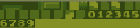
So we can easily remember where the digits start, let’s add a constant called DIGIT_OFFSET to point us to where the digits are relative to the start of the tile set: $1A
DEF BRICK_LEFT EQU $05
DEF BRICK_RIGHT EQU $06
DEF BLANK_TILE EQU $08
DEF DIGIT_OFFSET EQU $1A
Let’s make an assumption, that we cannot get a score higher than 99 (what could possibly go wrong) so two digits are enough.
We can start with showing two zeroes (the tile at offset $1A) on our initial map. Let’s put them on row 3, starting 4 tiles to the left.
You can copy-paste the tile set from this file
This should make the tile set look like this on start up:
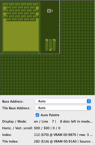
Tip: You can find the address in VRAM in your emulator’s tile map viewer by selecting the tile and looking at the index. The screenshot above is from emulucious.
Let’s remember their positions by defining a constant for VRAM location of the 10s and the 1s at the top of our file, behind the other constants.
DEF SCORE_TENS EQU $9870
DEF SCORE_ONES EQU $9871
Displaying the score
Now we need to write the missing UpdateScoreBoard function that will update the score board:
; Read the packed BCD score from wScore and updates the score display
UpdateScoreBoard:
ld a, [wScore] ; Get the Packed score
and %11110000 ; Mask the lower nibble
swap a ; Move the upper nibble to the lower nibble (divide by 16)
add a, DIGIT_OFFSET ; Offset + add to get the digit tile
ld [SCORE_TENS], a ; Show the digit on screen
ld a, [wScore] ; Get the packed score again
and %00001111 ; Mask the upper nibble
add a, DIGIT_OFFSET ; Offset + add to get the digit tile again
ld [SCORE_ONES], a ; Show the digit on screen
ret
First we load the score (stored in the wScore memory location) into register A. Recall that the score is stored in packed BCD format, where the upper nibble contains the tens digit and the lower nibble contains the ones digit.
The and %11110000 operation masks the lower nibble (the ones digit) so that only the upper nibble (the tens digit) remains in A.
The swap a instruction swaps the upper nibble with the lower four bits, leaving the tens digit ready for us to display.
We then add the DIGIT_OFFSET constant to the tens digit to calculate the tile address for the digit. This address is stored in the SCORE_TENS VRAM location, which updates the display to show the tens digit.
Finally, we repeat the process for the ones digit: We mask the tens digit from A using and %00001111, no need to rotate this time.
Now we can display the score on the screen! We’ll need to call UpdateScoreBoard after each time the score is updated. We’ve already done this in the IncreaseScorePackedBCD function, so we’re all set!
Work in progress
🚧 🚧 🚧 🚧 🚧 🚧 🚧
As explained in the initial tutorial presentation, Part Ⅱ consists of us building an Arkanoid game. However, this is not finished yet; lessons are uploaded as they are made, so the tutorial just abruptly stops at some point. Sorry!
Please hold tight while we are working on this, follow us on Twitter for updates, and go to the next page to find out what you can do in the meantime!
Thank you for your patience 😊 and see you around on GBDev!
Introducing Galactic Armada

This guide will help you create a classic shoot-em-up in RGBDS. This guide builds on knowledge from the previous tutorials, so some basic (or previously explained) concepts will not be explained.
Feature set
Here’s a list of features that will be included in the final product.
- Vertical Scrolling Background
- Basic HUD (via Window) & Score
- 4-Directional Player Movement
- Enemies
- Bullets
- Enemy/Bullet Collision
- Enemy/Player Collision
- Smooth Movement via Scaled Integers - Instead of using counters, smoother motion can be achieved using 16-bit (scaled) integers.
- Multiple Game States: Title Screen, Gameplay, Story State
- STAT Interrupts - used to properly draw the HUD at the top of gameplay.
- RGBGFX & INCBIN
- Writing Text
Project Structure
This page is going to give you an idea of how the Galactic Armada project is structured. This includes the folders, resources, tools, entry point, and compilation process.
The code can be found at https://github.com/gbdev/gb-asm-tutorial/tree/master/galactic-armada.
Folder Layout
For organizational purposes, many parts of the logic are separated into reusable functions. This is to reduce duplicate code, and make logic more clear.
Here’s a basic look at how the project is structured:
Generated files should never be included in VCS repositories. It unneccessarily bloats the repo. The folders below marked with * contains assets generated from running the Makefile and are not included in the repository.
libs- Two assembly files for input and sprites are located here.srcgenerated- the results of RGBGFX are stored here. *resources- Here exist some PNGs and Aseprite files for usage with RGBGFXmain- All assembly files are located here, or in subfoldersstatesgameplay- for gameplay related filesobjects- for gameplay objects like the player, bullets, and enemies- collision - for collision among objects
story- for our story state’s related filestitle-screen- for our title screen’s related files
utils- Extra functions includes to assist with developmentmacros
dist- The final ROM file will be created here. *obj- Intermediate files from the compile process. *Makefile- used to create the final ROM file and intermediate files
Background & Sprite Resources
The following backgrounds and sprites are used in Galactic Armada:
- Backgrounds
- Star Field
- Title Screen
- Text Font (Tiles only)
- Sprites
- Enemy Ship
- Player Ship
- Bullet


These images were originally created in Aseprite. The original templates are also included in the repository. They were exported as a PNG with a specific color palette. Ater being exported as a PNG, when you run make, they are converted into .2bpp and .tilemap files via the RGBDS tool: RGBGFX.
The
rgbgfxprogram converts PNG images into data suitable for display on the Game Boy and Game Boy Color, or vice-versa.The main function of
rgbgfxis to divide the input PNG into 8×8 pixel squares, convert each of those squares into 1bpp or 2bpp tile data, and save all of the tile data in a file. It also has options to generate a tile map, attribute map, and/or palette set as well; more on that and how the conversion process can be tweaked below.
RGBGFX can be found here: https://rgbds.gbdev.io/docs/v0.6.1/rgbgfx.1
We’ll use it to convert all of our graphics to .2bpp, and .tilemap formats (binary files)
NEEDED_GRAPHICS = \
$(GENSPRITES)/player-ship.2bpp \
$(GENSPRITES)/enemy-ship.2bpp \
$(GENSPRITES)/bullet.2bpp \
$(GENBACKGROUNDS)/text-font.2bpp \
$(GENBACKGROUNDS)/star-field.tilemap \
$(GENBACKGROUNDS)/title-screen.tilemap
# Generate sprites, ensuring the containing directories have been created.
$(GENSPRITES)/%.2bpp: $(RESSPRITES)/%.png | $(GENSPRITES)
$(GFX) -c "#FFFFFF,#cfcfcf,#686868,#000000;" --columns -o $@ $<
# Generate background tile set, ensuring the containing directories have been created.
$(GENBACKGROUNDS)/%.2bpp: $(RESBACKGROUNDS)/%.png | $(GENBACKGROUNDS)
$(GFX) -c "#FFFFFF,#cbcbcb,#414141,#000000;" -o $@ $<
# Generate background tile map *and* tile set, ensuring the containing directories
# have been created.
$(GENBACKGROUNDS)/%.tilemap: $(RESBACKGROUNDS)/%.png | $(GENBACKGROUNDS)
$(GFX) -c "#FFFFFF,#cbcbcb,#414141,#000000;" \
--tilemap $@ \
--unique-tiles \
-o $(GENBACKGROUNDS)/$*.2bpp \
$<
From there, INCBIN commands are used to store reference the binary tile data.
; in src/main/states/gameplay/objects/player.asm
playerShipTileData: INCBIN "src/generated/sprites/player-ship.2bpp"
playerShipTileDataEnd:
; in src/main/states/gameplay/objects/enemies.asm
enemyShipTileData:: INCBIN "src/generated/sprites/enemy-ship.2bpp"
enemyShipTileDataEnd::
; in src/main/states/gameplay/objects/bullets.asm
bulletTileData:: INCBIN "src/generated/sprites/bullet.2bpp"
bulletTileDataEnd::
Including binary files
You probably have some graphics, level data, etc. you’d like to include. Use INCBIN to include a raw binary file as it is. If the file isn’t found in the current directory, the include-path list passed to rgbasm(1) (see the -i option) on the command line will be searched.
INCBIN "titlepic.bin"
INCBIN "sprites/hero.bin"
You can also include only part of a file with INCBIN. The example below includes 256 bytes from data.bin, starting from byte 78.
INCBIN "data.bin",78,256
The length argument is optional. If only the start position is specified, the bytes from the start position until the end of the file will be included.
Compilation
Compilation is done via a Makefile. This Makefile can be run using the make command. Make should be preinstalled on Linux and Mac systems. For Windows users, check out cygwin.
Without going over everything in detail, here’s what the Makefile does:
- Clean generated folders
- Recreate generated folders
- Convert PNGs in src/resources to
.2bpp, and.tilemapformats - Convert
.asmfiles to.o - Use the
.ofiles to build the ROM file - Apply the RGBDS “fix” utility.
Entry Point
We’ll start this tutorial out like the previous, with our “header” section (at address: $100). We’re also going to declare some global variables that will be used throughout the game.
wLastKeysandwCurKeysare used for joypad inputwGameStatewill keep track what our current game state is
INCLUDE "src/main/utils/hardware.inc"
SECTION "GameVariables", WRAM0
wLastKeys:: db
wCurKeys:: db
wNewKeys:: db
wGameState::db
SECTION "Header", ROM0[$100]
jp EntryPoint
ds $150 - @, 0 ; Make room for the header
EntryPoint:
after our EntryPoint label, well do the following:
- set our default game state
- initiate gb-sprobj-lib, the sprite library we’re going to use
- setup our display registers
- load tile data for our font into VRAM.
The tile data we are going to load is used by all game states, which is why we’ll do it here & now, for them all to use.

This character-set is called “Area51”. It, and more 8x8 pixel fonts can ne found here: https://damieng.com/typography/zx-origins/ . These 52 tiles will be placed at the beginning of our background/window VRAM region.
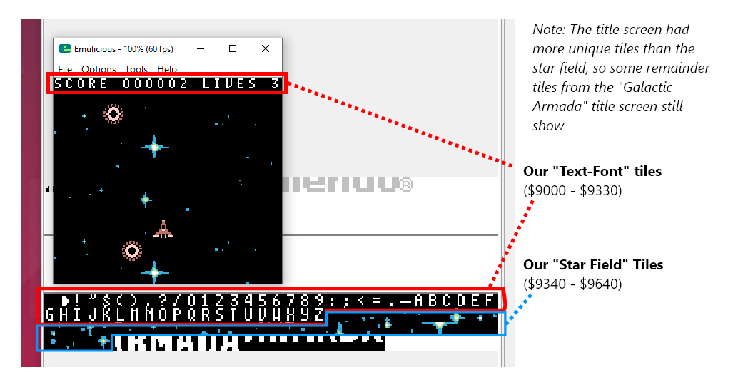
One important thing to note. Character maps for each letter must be defined. This let’s RGBDS know what byte value to give a specific letter.
For the Galactic Armada space mapping, we’re going off the “text-font.png” image. Our space character is the first character in VRAM. Our alphabet starts at 26. Special additions could be added if desired. For now, this is all that we’ll need. We’ll define that map in “src/main/utils/macros/text-macros.inc”.
; The character map for the text-font
CHARMAP " ", 0
CHARMAP ".", 24
CHARMAP "-", 25
CHARMAP "a", 26
CHARMAP "b", 27
CHARMAP "c", 28
CHARMAP "d", 29
CHARMAP "e", 30
CHARMAP "f", 31
CHARMAP "g", 32
CHARMAP "h", 33
CHARMAP "i", 34
CHARMAP "j", 35
CHARMAP "k", 36
CHARMAP "l", 37
CHARMAP "m", 38
CHARMAP "n", 39
CHARMAP "o", 40
CHARMAP "p", 41
CHARMAP "q", 42
CHARMAP "r", 43
CHARMAP "s", 44
CHARMAP "t", 45
CHARMAP "u", 46
CHARMAP "v", 47
CHARMAP "w", 48
CHARMAP "x", 49
CHARMAP "y", 50
CHARMAP "z", 51
Getting back to our entry point. Were going to wait until a vertical blank begins to do all of this. We’ll also turn the LCD off before loading our tile data into VRAM..
; Shut down audio circuitry
xor a
ld [rNR52], a
; We don't actually need another xor a here, because the value of A doesn't change between these two instructions
ld [wGameState], a
; Wait for the vertical blank phase before initiating the library
call WaitForOneVBlank
; from: https://github.com/eievui5/gb-sprobj-lib
; The library is relatively simple to get set up. First, put the following in your initialization code:
; Initilize Sprite Object Library.
call InitSprObjLibWrapper
; Turn the LCD off
xor a
ld [rLCDC], a
; Load our common text font into VRAM
call LoadTextFontIntoVRAM
; Turn the LCD on
ld a, LCDCF_ON | LCDCF_BGON|LCDCF_OBJON | LCDCF_OBJ16 | LCDCF_WINON | LCDCF_WIN9C00
ld [rLCDC], a
; During the first (blank) frame, initialize display registers
ld a, %11100100
ld [rBGP], a
ld [rOBP0], a
Even though we haven’t specifically defined a color palette. The emulicious emulator may automatically apply a default color palette if in “Automatic” or “Gameboy Color” mode.
Instead of ld a, 0, we can use xor a to set a to 0. It takes one byte less, which matters a lot on the Game Boy.
In the above snippet you saw use of a function called WaitFOrOneVBLank. We’ve setup some vblank utility functions in the “src/main/utils/vblank-utils.asm” file:
INCLUDE "src/main/utils/hardware.inc"
SECTION "VBlankVariables", WRAM0
wVBlankCount:: db
SECTION "VBlankFunctions", ROM0
WaitForOneVBlank::
; Wait a small amount of time
; Save our count in this variable
ld a, 1
ld [wVBlankCount], a
WaitForVBlankFunction::
WaitForVBlankFunction_Loop::
ld a, [rLY] ; Copy the vertical line to a
cp 144 ; Check if the vertical line (in a) is 0
jp c, WaitForVBlankFunction_Loop ; A conditional jump. The condition is that 'c' is set, the last operation overflowed
ld a, [wVBlankCount]
sub 1
ld [wVBlankCount], a
ret z
WaitForVBlankFunction_Loop2::
ld a, [rLY] ; Copy the vertical line to a
cp 144 ; Check if the vertical line (in a) is 0
jp nc, WaitForVBlankFunction_Loop2 ; A conditional jump. The condition is that 'c' is set, the last operation overflowed
jp WaitForVBlankFunction_Loop
In the next section, we’ll go on next to setup our NextGameState label. Which is used for changing game states.
Changing Game States
In our GalacticArmada.asm file, we’ll define label called “NextGameState”. Our game will have 3 game states:
- Title Screen
- Story Screen
- Gameplay
Here is how they will flow:
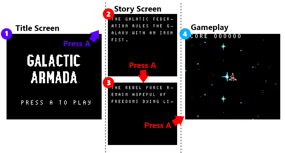
When one game state wants to go to another, it will need to change our previously declared ‘wGameState’ variable and then jump to the “NextGameState” label. There are some common things we want to accomplish when changing game states:
(during a Vertical Blank)
- Turn off the LCD
- Reset our Background & Window positions
- Clear the Background
- Disable Interrupts
- Clear All Sprites
- Initiate our NEXT game state
- Jump to our NEXT game state’s (looping) update logic
It will be the responsibility of the “init” function for each game state to turn the LCD back on.
NextGameState::
; Do not turn the LCD off outside of VBlank
call WaitForOneVBlank
call ClearBackground
; Turn the LCD off
xor a
ld [rLCDC], a
ld [rSCX], a
ld [rSCY], a
ld [rWX], a
ld [rWY], a
; disable interrupts
call DisableInterrupts
; Clear all sprites
call ClearAllSprites
; Initiate the next state
ld a, [wGameState]
cp 2 ; 2 = Gameplay
call z, InitGameplayState
ld a, [wGameState]
cp 1 ; 1 = Story
call z, InitStoryState
ld a, [wGameState]
and a ; 0 = Menu
call z, InitTitleScreenState
; Update the next state
ld a, [wGameState]
cp 2 ; 2 = Gameplay
jp z, UpdateGameplayState
cp 1 ; 1 = Story
jp z, UpdateStoryState
jp UpdateTitleScreenState
The goal here is to ( as much as possible) give each new game state a blank slate to start with.
That’s it for the GalacticArmada.asm file.
Title Screen
The title screen shows a basic title image using the background and draws text asking the player to press A. Once the user presses A, it will go to the story screen.
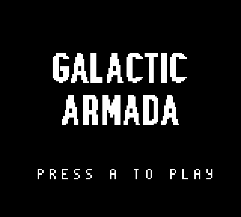
Our title screen has 3 pieces of data:
- The “Press A to play” text
- The title screen tile data
- The title screen tilemap
INCLUDE "src/main/utils/hardware.inc"
INCLUDE "src/main/utils/macros/text-macros.inc"
SECTION "TitleScreenState", ROM0
PressPlayText:: db "press a to play", 255
titleScreenTileData: INCBIN "src/generated/backgrounds/title-screen.2bpp"
titleScreenTileDataEnd:
titleScreenTileMap: INCBIN "src/generated/backgrounds/title-screen.tilemap"
titleScreenTileMapEnd:
Initiating the Title Screen
In our title screen’s “InitTitleScreen” function, we’ll do the following:
- draw the title screen graphic
- draw our “Press A to play”
- turn on the LCD.
Here is what our “InitTitleScreenState” function looks like
InitTitleScreenState::
call DrawTitleScreen
;;;;;;;;;;;;;;;;;;;;;;;;;;;;;;;;;;;;;;;;;;;;;;;;;;;;;;;;;;;;;;;;;;;;;;;;;;;;;;;;;;;;;;;;;
; Draw the press play text
;;;;;;;;;;;;;;;;;;;;;;;;;;;;;;;;;;;;;;;;;;;;;;;;;;;;;;;;;;;;;;;;;;;;;;;;;;;;;;;;;;;;;;;;;
; Call Our function that draws text onto background/window tiles
ld de, $99C3
ld hl, PressPlayText
call DrawTextTilesLoop
;;;;;;;;;;;;;;;;;;;;;;;;;;;;;;;;;;;;;;;;;;;;;;;;;;;;;;;;;;;;;;;;;;;;;;;;;;;;;;;;;;;;;;;;;
;;;;;;;;;;;;;;;;;;;;;;;;;;;;;;;;;;;;;;;;;;;;;;;;;;;;;;;;;;;;;;;;;;;;;;;;;;;;;;;;;;;;;;;;;
;;;;;;;;;;;;;;;;;;;;;;;;;;;;;;;;;;;;;;;;;;;;;;;;;;;;;;;;;;;;;;;;;;;;;;;;;;;;;;;;;;;;;;;;;
; Turn the LCD on
ld a, LCDCF_ON | LCDCF_BGON|LCDCF_OBJON | LCDCF_OBJ16
ld [rLCDC], a
ret
In order to draw text in our game, we’ve created a function called “DrawTextTilesLoop”. We’ll pass this function which tile to start on in de, and the address of our text in hl.
DrawTextTilesLoop::
; Check for the end of string character 255
ld a, [hl]
cp 255
ret z
; Write the current character (in hl) to the address
; on the tilemap (in de)
ld a, [hl]
ld [de], a
inc hl
inc de
; move to the next character and next background tile
jp DrawTextTilesLoop
The “DrawTitleScreen” function puts the tiles for our title screen graphic in VRAM, and draws its tilemap to the background:
NOTE: Because of the text font, we’ll add an offset of 52 to our tilemap tiles. We’ve created a function that adds the 52 offset, since we’ll need to do so more than once.
DrawTitleScreen::
; Copy the tile data
ld de, titleScreenTileData ; de contains the address where data will be copied from;
ld hl, $9340 ; hl contains the address where data will be copied to;
ld bc, titleScreenTileDataEnd - titleScreenTileData ; bc contains how many bytes we have to copy.
call CopyDEintoMemoryAtHL
; Copy the tilemap
ld de, titleScreenTileMap
ld hl, $9800
ld bc, titleScreenTileMapEnd - titleScreenTileMap
jp CopyDEintoMemoryAtHL_With52Offset
The “CopyDEintoMemoryAtHL” and “CopyDEintoMemoryAtHL_With52Offset” functions are defined in “src/main/utils/memory-utils.asm”:
SECTION "MemoryUtilsSection", ROM0
CopyDEintoMemoryAtHL::
ld a, [de]
ld [hli], a
inc de
dec bc
ld a, b
or c
jp nz, CopyDEintoMemoryAtHL ; Jump to CopyTiles if the last operation had a non zero result.
ret
CopyDEintoMemoryAtHL_With52Offset::
ld a, [de]
add a, 52
ld [hli], a
inc de
dec bc
ld a, b
or c
jp nz, CopyDEintoMemoryAtHL_With52Offset ; Jump to COpyTiles, if the z flag is not set. (the last operation had a non zero result)
ret
Updating the Title Screen
The title screen’s update logic is the simplest of the 3. All we are going to do is wait until the A button is pressed. Afterwards, we’ll go to the story screen game state.
UpdateTitleScreenState::
;;;;;;;;;;;;;;;;;;;;;;;;;;;;;;;;;;;;;;;;;;;;;;;;;;;;;;;;;;;;;;;;;;;;;;;;;;;;;;;;;;;;;;;;;
; Wait for A
;;;;;;;;;;;;;;;;;;;;;;;;;;;;;;;;;;;;;;;;;;;;;;;;;;;;;;;;;;;;;;;;;;;;;;;;;;;;;;;;;;;;;;;;;
; Save the passed value into the variable: mWaitKey
; The WaitForKeyFunction always checks against this vriable
ld a, PADF_A
ld [mWaitKey], a
call WaitForKeyFunction
;;;;;;;;;;;;;;;;;;;;;;;;;;;;;;;;;;;;;;;;;;;;;;;;;;;;;;;;;;;;;;;;;;;;;;;;;;;;;;;;;;;;;;;;;
;;;;;;;;;;;;;;;;;;;;;;;;;;;;;;;;;;;;;;;;;;;;;;;;;;;;;;;;;;;;;;;;;;;;;;;;;;;;;;;;;;;;;;;;;
ld a, 1
ld [wGameState],a
jp NextGameState
Our “WaitForKeyFunction” is defined in “src/main/utils/input-utils.asm”. We’ll poll for input and infinitely loop until the specified button is pressed down.
SECTION "InputUtilsVariables", WRAM0
mWaitKey:: db
SECTION "InputUtils", ROM0
WaitForKeyFunction::
; Save our original value
push bc
WaitForKeyFunction_Loop:
; save the keys last frame
ld a, [wCurKeys]
ld [wLastKeys], a
; This is in input.asm
; It's straight from: https://gbdev.io/gb-asm-tutorial/part2/input.html
; In their words (paraphrased): reading player input for gameboy is NOT a trivial task
; So it's best to use some tested code
call Input
ld a, [mWaitKey]
ld b, a
ld a, [wCurKeys]
and b
jp z, WaitForKeyFunction_NotPressed
ld a, [wLastKeys]
and b
jp nz, WaitForKeyFunction_NotPressed
; restore our original value
pop bc
ret
WaitForKeyFunction_NotPressed:
;;;;;;;;;;;;;;;;;;;;;;;;;;;;;;;;;;;;;;;;;;;;;;;;;;;;;;;;;;;;;;;;;;;;;;;;;;;;;;;;;
; Wait a small amount of time
; Save our count in this variable
ld a, 1
ld [wVBlankCount], a
; Call our function that performs the code
call WaitForVBlankFunction
;;;;;;;;;;;;;;;;;;;;;;;;;;;;;;;;;;;;;;;;;;;;;;;;;;;;;;;;;;;;;;;;;;;;;;;;;;;;;;;;;
jp WaitForKeyFunction_Loop
That’s it for our title screen. Next up is our story screen.
Story Screen
The story screen shows a basic story on 2 pages. Afterwards, it sends the player to the gameplay game state.
Initiating up the Story Screen
In the InitStoryState we’ll just going to turn on the LCD. Most of the game state’s logic will occur in its update function.
The text macros file is included so our story text has the proper character maps.
INCLUDE "src/main/utils/hardware.inc"
INCLUDE "src/main/utils/macros/text-macros.inc"
SECTION "StoryStateASM", ROM0
InitStoryState::
; Turn the LCD on
ld a, LCDCF_ON | LCDCF_BGON|LCDCF_OBJON | LCDCF_OBJ16
ld [rLCDC], a
ret
Updating the Story Screen
Here’s the data for our story screen. We have this defined just above our UpdateStoryState function:
Story:
.Line1 db "the galatic empire", 255
.Line2 db "rules the galaxy", 255
.Line3 db "with an iron", 255
.Line4 db "fist.", 255
.Line5 db "the rebel force", 255
.Line6 db "remain hopeful of", 255
.Line7 db "freedoms light", 255
The story text is shown using a typewriter effect. This effect is done similarly to the “press a to play” text that was done before, but here we wait for 3 vertical blank phases between writing each letter, giving some additional delay.
You could bind this to a variable and make it configurable via an options screen too!
For this effect, we’ve defined a function in our “src/main/utils/text-utils.asm” file:
DrawText_WithTypewriterEffect::
;;;;;;;;;;;;;;;;;;;;;;;;;;;;;;;;;;;;;;;;;;;;;;;;;;;;;;;;;;;;;;;;;;;;;;;;;;;;;;;;;
; Wait a small amount of time
; Save our count in this variable
ld a, 3
ld [wVBlankCount], a
; Call our function that performs the code
call WaitForVBlankFunction
;;;;;;;;;;;;;;;;;;;;;;;;;;;;;;;;;;;;;;;;;;;;;;;;;;;;;;;;;;;;;;;;;;;;;;;;;;;;;;;;;
; Check for the end of string character 255
ld a, [hl]
cp 255
ret z
; Write the current character (in hl) to the address
; on the tilemap (in de)
ld a, [hl]
ld [de], a
; move to the next character and next background tile
inc hl
inc de
jp DrawText_WithTypewriterEffect
We’ll call the DrawText_WithTypewriterEffect function exactly how we called the DrawTextTilesLoop function. We’ll pass this function which tile to start on in de, and the address of our text in hl.
We’ll do that four times for the first page, and then wait for the A button to be pressed:
UpdateStoryState::
; Call Our function that typewrites text onto background/window tiles
ld de, $9821
ld hl, Story.Line1
call DrawText_WithTypewriterEffect
; Call Our function that typewrites text onto background/window tiles
ld de, $9861
ld hl, Story.Line2
call DrawText_WithTypewriterEffect
; Call Our function that typewrites text onto background/window tiles
ld de, $98A1
ld hl, Story.Line3
call DrawText_WithTypewriterEffect
; Call Our function that typewrites text onto background/window tiles
ld de, $98E1
ld hl, Story.Line4
call DrawText_WithTypewriterEffect
;;;;;;;;;;;;;;;;;;;;;;;;;;;;;;;;;;;;;;;;;;;;;;;;;;;;;;;;;;;;;;;;;;;;;;;;;;;;;;;;;;;;;;;;;
; Wait for A
;;;;;;;;;;;;;;;;;;;;;;;;;;;;;;;;;;;;;;;;;;;;;;;;;;;;;;;;;;;;;;;;;;;;;;;;;;;;;;;;;;;;;;;;;
; Save the passed value into the variable: mWaitKey
; The WaitForKeyFunction always checks against this vriable
ld a, PADF_A
ld [mWaitKey], a
call WaitForKeyFunction
;;;;;;;;;;;;;;;;;;;;;;;;;;;;;;;;;;;;;;;;;;;;;;;;;;;;;;;;;;;;;;;;;;;;;;;;;;;;;;;;;;;;;;;;;
Once the user presses the A button, we want to show the second page. To avoid any lingering “leftover” letters, we’ll clear the background. All this function does is turn off the LCD, fill our background tilemap with the first tile, then turn back on the lcd. We’ve defined this function in the “src/main/utils/background.utils.asm” file:
include "src/main/utils/hardware.inc"
SECTION "Background", ROM0
ClearBackground::
; Turn the LCD off
xor a
ld [rLCDC], a
ld bc, 1024
ld hl, $9800
ClearBackgroundLoop:
xor a
ld [hli], a
dec bc
ld a, b
or c
jp nz, ClearBackgroundLoop
; Turn the LCD on
ld a, LCDCF_ON | LCDCF_BGON|LCDCF_OBJON | LCDCF_OBJ16
ld [rLCDC], a
ret
Getting back to our Story Screen: After we’ve shown the first page and cleared the background, we’ll do the same thing for page 2:
; Call Our function that typewrites text onto background/window tiles
ld de, $9821
ld hl, Story.Line5
call DrawText_WithTypewriterEffect
; Call Our function that typewrites text onto background/window tiles
ld de, $9861
ld hl, Story.Line6
call DrawText_WithTypewriterEffect
; Call Our function that typewrites text onto background/window tiles
ld de, $98A1
ld hl, Story.Line7
call DrawText_WithTypewriterEffect
;;;;;;;;;;;;;;;;;;;;;;;;;;;;;;;;;;;;;;;;;;;;;;;;;;;;;;;;;;;;;;;;;;;;;;;;;;;;;;;;;;;;;;;;;
; Wait for A
;;;;;;;;;;;;;;;;;;;;;;;;;;;;;;;;;;;;;;;;;;;;;;;;;;;;;;;;;;;;;;;;;;;;;;;;;;;;;;;;;;;;;;;;;
; Save the passed value into the variable: mWaitKey
; The WaitForKeyFunction always checks against this vriable
ld a, PADF_A
ld [mWaitKey], a
call WaitForKeyFunction
;;;;;;;;;;;;;;;;;;;;;;;;;;;;;;;;;;;;;;;;;;;;;;;;;;;;;;;;;;;;;;;;;;;;;;;;;;;;;;;;;;;;;;;;;
With our story full shown, we’re ready to move onto the next game state: Gameplay. We’ll end our UpdateStoryState function by updating our game state variable and jump back to the NextGameState label like previously discussed.
ld a, 2
ld [wGameState],a
jp NextGameState
Gameplay State
In this game state, the player will control a spaceship. Flying over a vertically scrolling space background. They’ll be able to freely move in 4 directions , and shoot oncoming alien ships. As alien ships are destroyed by bullets, the player’s score will increase.
Gameplay is the core chunk of the source code. It also took the most time to create. Because of such, this game state has to be split into multiple sub-pages. Each page will explain a different gameplay concept.
Our gameplay state defines the following data and variables:
INCLUDE "src/main/utils/hardware.inc"
INCLUDE "src/main/utils/macros/text-macros.inc"
SECTION "GameplayVariables", WRAM0
wScore:: ds 6
wLives:: db
SECTION "GameplayState", ROM0
wScoreText:: db "score", 255
wLivesText:: db "lives", 255
For simplicity reasons, our score uses 6 bytes. Each byte repesents one digit in the score.
Initiating the Gameplay Game State:
When gameplay starts we want to do all of the following:
- reset the player’s score to 0
- reset the player’s lives to 3.
- Initialize all of our gameplay elements ( background, player, bullets, and enemies)
- Enable STAT interrupts for the HUD
- Draw our “score” & “lives” on the HUD.
- Reset the window’s position back to 7,0
- Turn the LCD on with the window enabled at $9C00
InitGameplayState::
ld a, 3
ld [wLives], a
xor a
ld [wScore], a
ld [wScore+1], a
ld [wScore+2], a
ld [wScore+3], a
ld [wScore+4], a
ld [wScore+5], a
call InitializeBackground
call InitializePlayer
call InitializeBullets
call InitializeEnemies
; Initiate STAT interrupts
call InitStatInterrupts
;;;;;;;;;;;;;;;;;;;;;;;;;;;;;;;;;;;;;;;;;;;;;;;;;;;;;;;;;;;;;;;;;;;;;;;;;;;;;;;;;;;;;;;
;;;;;;;;;;;;;;;;;;;;;;;;;;;;;;;;;;;;;;;;;;;;;;;;;;;;;;;;;;;;;;;;;;;;;;;;;;;;;;;;;;;;;;;
; Call Our function that draws text onto background/window tiles
ld de, $9c00
ld hl, wScoreText
call DrawTextTilesLoop
; Call Our function that draws text onto background/window tiles
ld de, $9c0d
ld hl, wLivesText
call DrawTextTilesLoop
;;;;;;;;;;;;;;;;;;;;;;;;;;;;;;;;;;;;;;;;;;;;;;;;;;;;;;;;;;;;;;;;;;;;;;;;;;;;;;;;;;;;;;;
;;;;;;;;;;;;;;;;;;;;;;;;;;;;;;;;;;;;;;;;;;;;;;;;;;;;;;;;;;;;;;;;;;;;;;;;;;;;;;;;;;;;;;;
call DrawScore
call DrawLives
ld a, 0
ld [rWY], a
ld a, 7
ld [rWX], a
; Turn the LCD on
ld a, LCDCF_ON | LCDCF_BGON|LCDCF_OBJON | LCDCF_OBJ16 | LCDCF_WINON | LCDCF_WIN9C00|LCDCF_BG9800
ld [rLCDC], a
ret
The initialization logic for our the background, the player, the enemies, the bullets will be explained in later pages. Every game state is responsible for turning the LCD back on. The gameplay game state needs to use the window layer, so we’ll make sure that’s enabled before we return.
Updating the Gameplay Game State
Our “UpdateGameplayState” function doesn’t have very complicated logic. Most of the logic has been split into separate files for the background, player, enemies, and bullets.
During gameplay, we do all of the following:
- Poll for input
- Reset our Shadow OAM
- Reset our current shadow OAM sprite
- Update our gameplay elements (player, background, enemies, bullets, background)
- Remove any unused sprites from the screen
- End gameplay if we’ve lost all of our lives
- inside of the vertical blank phase
- Apply shadow OAM sprites
- Update our background tilemap’s position
We’ll poll for input like in the previous tutorial. We’ll always save the previous state of the gameboy’s buttons in the “wLastKeys” variable.
UpdateGameplayState::
; save the keys last frame
ld a, [wCurKeys]
ld [wLastKeys], a
; This is in input.asm
; It's straight from: https://gbdev.io/gb-asm-tutorial/part2/input.html
; In their words (paraphrased): reading player input for gameboy is NOT a trivial task
; So it's best to use some tested code
call Input
Next, we’ll reset our Shadow OAM and reset current Shadow OAM sprite address.
; from: https://github.com/eievui5/gb-sprobj-lib
; hen put a call to ResetShadowOAM at the beginning of your main loop.
call ResetShadowOAM
call ResetOAMSpriteAddress
Because we are going to be dealing with a lot of sprites on the screen, we will not be directly manipulating the gameboy’s OAM sprites. We’ll define a set of “shadow” (copy“) OAM sprites, that all objects will use instaed. At the end of the gameplay looop, we’ll copy the shadow OAM sprite objects into the hardware.
Each object will use a random shadow OAM sprite. We need a way to keep track of what shadow OAM sprite is being used currently. For this, we’ve created a 16-bit pointer called “wLastOAMAddress”. Defined in “src/main/utils/sprites.asm”, this points to the data for the next inactive shadow OAM sprite.
When we reset our current Shadow OAM sprite address, we just set the “mLastOAMAddress” RAM variable to point to the first shadow OAM sprite.
NOTE: We also keep a counter on how many shadow OAM sprites are used. In our “ResetOAMSpriteAddress” function, we’ll reset that counter too.
ResetOAMSpriteAddress::
xor a
ld [wSpritesUsed], a
ld a, LOW(wShadowOAM)
ld [wLastOAMAddress], a
ld a, HIGH(wShadowOAM)
ld [wLastOAMAddress+1], a
ret
Next we’ll update our gameplay elements:
call UpdatePlayer
call UpdateEnemies
call UpdateBullets
call UpdateBackground
After all of that, at this point in time, the majority of gameplay is done for this iteration. We’ll clear any remaining spirtes. This is very necessary becaus the number of active sprites changes from frame to frame. If there are any visible OAM sprites left onscreen, they will look weird and/or mislead the player.
; Clear remaining sprites to avoid lingering rogue sprites
call ClearRemainingSprites
The clear remaining sprites function, for all remaining shadow OAM sprites, moves the sprite offscreen so they are no longer visible. This function starts at wherever the “wLastOAMAddress” variable last left-off.
End of The Gameplay loop
At this point in time, we need to check if gameplay needs to continue. When the vertical blank phase starts, we check if the player has lost all of their lives. If so, we end gameplay. We end gameplay similar to how we started it, we’ll update our ‘wGameState’ variable and jump to “NextGameState”.
If the player hasn’t lost all of their lives, we’ll copy our shadow OAM sprites over to the actual hardware OAM sprites and loop background.
ld a, [wLives]
cp 250
jp nc, EndGameplay
;;;;;;;;;;;;;;;;;;;;;;;;;;;;;;;;;;;;;;;;;;;;;;;;;;;;;;;;;;;;;;
; Call our function that performs the code
call WaitForOneVBlank
;;;;;;;;;;;;;;;;;;;;;;;;;;;;;;;;;;;;;;;;;;;;;;;;;;;;;;;;;;;;;;
; from: https://github.com/eievui5/gb-sprobj-lib
; Finally, run the following code during VBlank:
ld a, HIGH(wShadowOAM)
call hOAMDMA
;;;;;;;;;;;;;;;;;;;;;;;;;;;;;;;;;;;;;;;;;;;;;;;;;;;;;;;;;;;;;;
; Call our function that performs the code
call WaitForOneVBlank
;;;;;;;;;;;;;;;;;;;;;;;;;;;;;;;;;;;;;;;;;;;;;;;;;;;;;;;;;;;;;;
jp UpdateGameplayState
EndGameplay:
ld a, 0
ld [wGameState],a
jp NextGameState
Scrolling Background
Scrolling the background is an easy task. However, for a SMOOTH slow scrolling background: scaled integers1 will be used.
⚠️ Scaled Integers1 are a way to provide smooth “sub-pixel” movement. They are slightly more difficult to understand & implement than implementing a counter, but they provide smoother motion.
Initializing the Background
At the start of the gameplay game state we called the initialize background function. This function shows the star field background, and resets our background scroll variables:
Just like with our title screen graphic, because our text font tiles are at the beginning of VRAM: we offset the tilemap values by 52
INCLUDE "src/main/utils/hardware.inc"
INCLUDE "src/main/utils/macros/text-macros.inc"
SECTION "BackgroundVariables", WRAM0
mBackgroundScroll:: dw
SECTION "GameplayBackgroundSection", ROM0
starFieldMap: INCBIN "src/generated/backgrounds/star-field.tilemap"
starFieldMapEnd:
starFieldTileData: INCBIN "src/generated/backgrounds/star-field.2bpp"
starFieldTileDataEnd:
InitializeBackground::
; Copy the tile data
ld de, starFieldTileData ; de contains the address where data will be copied from;
ld hl, $9340 ; hl contains the address where data will be copied to;
ld bc, starFieldTileDataEnd - starFieldTileData ; bc contains how many bytes we have to copy.
call CopyDEintoMemoryAtHL
; Copy the tilemap
ld de, starFieldMap
ld hl, $9800
ld bc, starFieldMapEnd - starFieldMap
call CopyDEintoMemoryAtHL_With52Offset
xor a
ld [mBackgroundScroll], a
ld [mBackgroundScroll+1], a
ret
To scroll the background in a gameboy game, we simply need to gradually change the SCX or SCX registers. Our code is a tiny bit more complicated because of scaled integer usage. Our background’s scroll position is stored in a 16-bit integer called mBackgroundScroll. We’l increase that 16-bit integer by a set amount.
; This is called during gameplay state on every frame
UpdateBackground::
; Increase our scaled integer by 5
; Get our true (non-scaled) value, and save it for later usage in bc
ld a, [mBackgroundScroll]
add a, 5
ld b, a
ld [mBackgroundScroll], a
ld a, [mBackgroundScroll+1]
adc 0
ld c, a
ld [mBackgroundScroll+1], a
We won’t directly draw the background using this value. De-scaling a scaled integer simulates having a (more precise and useful for smooth movement) floating-point number. The value we draw our background at will be the de-scaled version of that 16-bit integer. To get that non-scaled version, we’ll simply shift all of it’s bit rightward 4 places. The final result will saved for when we update our background’s y position.
; Descale our scaled integer
; shift bits to the right 4 spaces
srl c
rr b
srl c
rr b
srl c
rr b
srl c
rr b
; Use the de-scaled low byte as the backgrounds position
ld a, b
ld [rSCY], a
ret
Heads Up Interface
The gameboy normally draws sprites over both the window and background, and the window over the background. In Galactic Armada, The background is vertically scrolling. This means the HUD (the score text and number) needs to be draw on the window, which is separate from the background.
On our HUD, we’ll draw both our score and our lives. We’ll also use STAT interrupts to make sure nothing covers the HUD.
STAT Interrupts & the window
The window is not enabled by default. We can enable the window using the LCDC register. RGBDS comes with constants that will help us.
⚠️ NOTE: The window can essentially be a copy of the background. The
LCDCF_WIN9C00|LCDCF_BG9800portion makes the background and window use different tilemaps when drawn. There’s only one problem. Since the window is drawn between sprites and the background. Without any extra effort, our scrolling background tilemap will be covered by our window. In addition, our sprites will be drawn over our hud. For this, we’ll need STAT interrupts. Fore more information on STAT interrupts, check out the pandocs: https://gbdev.io/pandocs/Interrupt_Sources.html
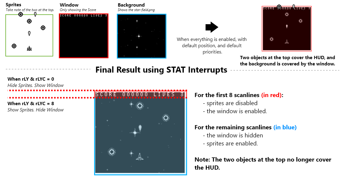
Using the STAT interrupt
One very popular use is to indicate to the user when the video hardware is about to redraw a given LCD line. This can be useful for dynamically controlling the SCX/SCY registers ($FF43/$FF42) to perform special video effects.
Example application: set LYC to WY, enable LY=LYC interrupt, and have the handler disable sprites. This can be used if you use the window for a text box (at the bottom of the screen), and you want sprites to be hidden by the text box.
With STAT interrupts, we can implement raster effects. in our case, we’ll enable the window and stop drawing sprites on the first 8 scanlines. Afterwards, we’ll show sprites and disable the window layer for the remaining scanlines. This makes sure nothing overlaps our HUD, and that our background is fully shown also.
Initiating & Disabling STAT interrupts
In our gameplay game state, at different points in time, we initialized and disabled interrupts. Here’s the logic for those functions in our “src/main/states/gameplay/hud.asm” file:
INCLUDE "src/main/utils/hardware.inc"
SECTION "Interrupts", ROM0
DisableInterrupts::
xor a
ldh [rSTAT], a
di
ret
InitStatInterrupts::
ld a, IEF_STAT
ldh [rIE], a
xor a
ldh [rIF], a
ei
; This makes our stat interrupts occur when the current scanline is equal to the rLYC register
ld a, STATF_LYC
ldh [rSTAT], a
; We'll start with the first scanline
; The first stat interrupt will call the next time rLY = 0
xor a
ldh [rLYC], a
ret
Defining STAT interrupts
Our actual STAT interrupts must be located at $0048. We’ll define different paths depending on what our LYC variable’s value is when executed.
; Define a new section and hard-code it to be at $0048.
SECTION "Stat Interrupt", ROM0[$0048]
StatInterrupt:
push af
; Check if we are on the first scanline
ldh a, [rLYC]
and a
jp z, LYCEqualsZero
LYCEquals8:
; Don't call the next stat interrupt until scanline 8
xor a
ldh [rLYC], a
; Turn the LCD on including sprites. But no window
ld a, LCDCF_ON | LCDCF_BGON | LCDCF_OBJON | LCDCF_OBJ16 | LCDCF_WINOFF | LCDCF_WIN9C00
ldh [rLCDC], a
jp EndStatInterrupts
LYCEqualsZero:
; Don't call the next stat interrupt until scanline 8
ld a, 8
ldh [rLYC], a
; Turn the LCD on including the window. But no sprites
ld a, LCDCF_ON | LCDCF_BGON | LCDCF_OBJOFF | LCDCF_OBJ16| LCDCF_WINON | LCDCF_WIN9C00
ldh [rLCDC], a
EndStatInterrupts:
pop af
reti;
That should be all it takes to get a properly drawn HUD. For more details, check out the code in the repo or ask questions on the gbdev discord server.
Keeping Score and Drawing Score on the HUD
To keep things simple, back in our gameplay game state, we used 6 different bytes to hold our score.Each byte will hold a value between 0 and 9, and represents a specific digit in the score. So it’s easy to loop through and edit the score number on the HUD: The First byte represents the left-most digit, and the last byte represents the right-most digit.
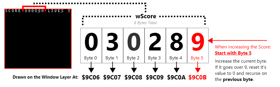
When the score increases, we’ll increase digits on the right. As they go higher than 9, we’ll reset back to 0 and increase the previous byte .
IncreaseScore::
; We have 6 digits, start with the right-most digit (the last byte)
ld c, 0
ld hl, wScore+5
IncreaseScore_Loop:
; Increase the digit
ld a, [hl]
inc a
ld [hl], a
; Stop if it hasn't gone past 0
cp 9
ret c
; If it HAS gone past 9
IncreaseScore_Next:
; Increase a counter so we can not go out of our scores bounds
inc c
ld a, c
; Check if we've gone over our scores bounds
cp 6
ret z
; Reset the current digit to zero
; Then go to the previous byte (visually: to the left)
ld a, 0
ld [hl], a
ld [hld], a
jp IncreaseScore_Loop
We can call that score whenever a bullet hits an enemy. This function however does not draw our score on the background. We do that the same way we drew text previously:
DrawScore::
; Our score has max 6 digits
; We'll start with the left-most digit (visually) which is also the first byte
ld c, 6
ld hl, wScore
ld de, $9C06 ; The window tilemap starts at $9C00
DrawScore_Loop:
ld a, [hli]
add 10 ; our numeric tiles start at tile 10, so add to 10 to each bytes value
ld [de], a
; Decrease how many numbers we have drawn
dec c
; Stop when we've drawn all the numbers
ret z
; Increase which tile we are drawing to
inc de
jp DrawScore_Loop
Because we’ll only ever have 3 lives, drawing our lives is much easier. The numeric characters in our text font start at 10, so we just need to put on the window, our lives plus 10.
DrawLives::
ld hl, wLives
ld de, $9C13 ; The window tilemap starts at $9C00
ld a, [hl]
add 10 ; our numeric tiles start at tile 10, so add 10 to each bytes value
ld [de], a
ret
Sprites & Metasprites
Before we dive into the player, bullets, and enemies; how they are drawn using metasprites should be explained.
For sprites, the following library is used: https://github.com/eievui5/gb-sprobj-lib
This is a small, lightweight library meant to facilitate the rendering of sprite objects, including Shadow OAM and OAM DMA, single-entry “simple” sprite objects, and Q12.4 fixed-point position metasprite rendering.
All objects are drawn using “metasprites”, or groups of sprites that define one single object. A custom “metasprite” implementation is used in addition. Metasprite definitions should a multiple of 4 plus one additional byte for the end.
- Relative Y offset ( relative to the previous sprite, or the actual metasprite’s draw position)
- Relative X offset ( relative to the previous sprite, or the actual metasprite’s draw position)
- Tile to draw
- Tile Props (not used in this project)
The logic stops drawing when it reads 128.
An example of metasprite is the enemy ship:
enemyShipMetasprite::
.metasprite1 db 0,0,4,0
.metasprite2 db 0,8,6,0
.metaspriteEnd db 128
![]()
The Previous snippet draws two sprites. One that the object’s actual position, which uses tile 4 and 5. The second sprite is 8 pixels to the right, and uses tile 6 and 7
⚠️ NOTE: Sprites are in 8x16 mode for this project.
I can later draw such metasprite by calling the “DrawMetasprite” function that
;;;;;;;;;;;;;;;;;;;;;;;;;;;;;;;;;;;;;;;;;;;;;;;;;;;;;;;;;;;;;;;;;;;;;;;;;;;;;;;;;;;;;;;
; call the 'DrawMetasprites function. setup variables and call
;;;;;;;;;;;;;;;;;;;;;;;;;;;;;;;;;;;;;;;;;;;;;;;;;;;;;;;;;;;;;;;;;;;;;;;;;;;;;;;;;;;;;;;;;;;;;
; Save the address of the metasprite into the 'wMetaspriteAddress' variable
; Our DrawMetasprites functoin uses that variable
ld a, LOW(enemyShipMetasprite)
ld [wMetaspriteAddress+0], a
ld a, HIGH(enemyShipMetasprite)
ld [wMetaspriteAddress+1], a
; Save the x position
ld a, [wCurrentEnemyX]
ld [wMetaspriteX], a
; Save the y position
ld a, [wCurrentEnemyY]
ld [wMetaspriteY], a
; Actually call the 'DrawMetasprites function
call DrawMetasprites
We previously mentioned a variable called “wLastOAMAddress”. The “DrawMetasprites” function can be found in the “src/main/utils/metasprites.asm” file:
include "src/main/utils/constants.inc"
SECTION "MetaSpriteVariables", WRAM0
wMetaspriteAddress:: dw
wMetaspriteX:: db
wMetaspriteY::db
SECTION "MetaSprites", ROM0
DrawMetasprites::
; get the metasprite address
ld a, [wMetaspriteAddress+0]
ld l, a
ld a, [wMetaspriteAddress+1]
ld h, a
; Get the y position
ld a, [hli]
ld b, a
; stop if the y position is 128
ld a, b
cp 128
ret z
ld a, [wMetaspriteY]
add b
ld [wMetaspriteY], a
; Get the x position
ld a, [hli]
ld c, a
ld a, [wMetaspriteX]
add c
ld [wMetaspriteX], a
; Get the tile position
ld a, [hli]
ld d, a
; Get the flag position
ld a, [hli]
ld e, a
; Get our offset address in hl
ld a,[wLastOAMAddress+0]
ld l, a
ld a, HIGH(wShadowOAM)
ld h, a
ld a, [wMetaspriteY]
ld [hli], a
ld a, [wMetaspriteX]
ld [hli], a
ld a, d
ld [hli], a
ld a, e
ld [hli], a
call NextOAMSprite
; increase the wMetaspriteAddress
ld a, [wMetaspriteAddress]
add a, METASPRITE_BYTES_COUNT
ld [wMetaspriteAddress], a
ld a, [wMetaspriteAddress+1]
adc 0
ld [wMetaspriteAddress+1], a
jp DrawMetasprites
When we call the “DrawMetasprites” function, the “wLastOAMAddress” variable will be advanced to point at the next available shadow OAM sprite. This is done using the “NextOAMSprite” function in “src/main/utils/sprites-utils.asm”
NextOAMSprite::
ld a, [wSpritesUsed]
inc a
ld [wSpritesUsed], a
ld a,[wLastOAMAddress]
add sizeof_OAM_ATTRS
ld [wLastOAMAddress], a
ld a, HIGH(wShadowOAM)
ld [wLastOAMAddress+1], a
ret
Object Pools
Galactic Armada will use “object pools” for bullets and enemies. A fixed amount of bytes representing a specific maximum amount of objects. Each pool is just a collection of bytes. The number of bytes per “pool” is the maximum number of objects in the pool, times the number of bytes needed for data for each object.
Constants are also created for the size of each object, and what each byte is. These constants are in the “src/main/utils/constants.inc” file and utilize RGBDS offset constants (a really cool feature)
; from https://rgbds.gbdev.io/docs/v0.6.1/rgbasm.5#EXPRESSIONS
; The RS group of commands is a handy way of defining structure offsets:
RSRESET
DEF bullet_activeByte RB 1
DEF bullet_xByte RB 1
DEF bullet_yLowByte RB 1
DEF bullet_yHighByte RB 1
DEF PER_BULLET_BYTES_COUNT RB 0
The two object types that we need to loop through are Enemies and Bullets.
Bytes for an Enemy:
- Active - Are they active
- X - Position: horizontal coordinate
- Y (low) - The lower byte of their 16-bit (scaled) y position
- Y (high) - The higher byte of their 16-bit (scaled) y position
- Speed - How fast they move
- Health - How many bullets they can take
; Bytes: active, x , y (low), y (high), speed, health
wEnemies:: ds MAX_ENEMY_COUNT*PER_ENEMY_BYTES_COUNT
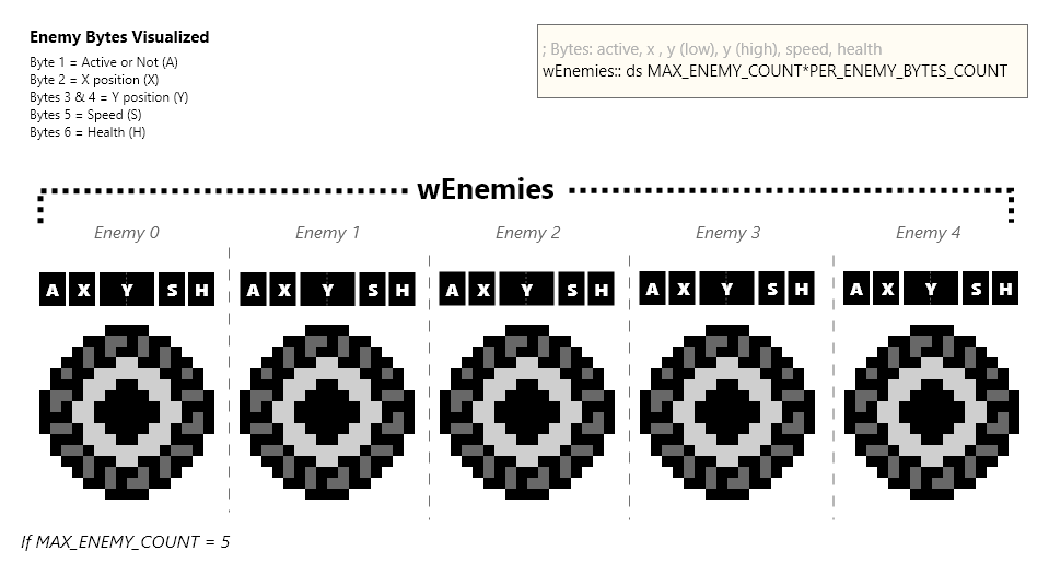
Bytes for a Bullet:
- Active - Are they active
- X - Position: horizontal coordinate
- Y (low) - The lower byte of their 16-bit (scaled) y position
- Y (high) - The higher byte of their 16-bit (scaled) y position
; Bytes: active, x , y (low), y (high)
wBullets:: ds MAX_BULLET_COUNT*PER_BULLET_BYTES_COUNT
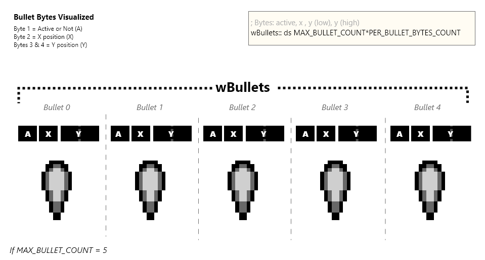
⚠️ NOTE: Scaled integers are used for only the y positions of bullets and enemies. Scaled Integers are a way to provide smooth “sub-pixel” movement. They only move vertically, so the x position can be 8-bit.
When looping through an object pool, we’ll check if an object is active. If it’s active, we’ll run the logic for that object. Otherwise, we’ll skip to the start of the next object’s bytes.
Both bullets and enemies do similar things. They move vertically until they are off the screen. In addition, enemies will check against bullets when updating. If they are found to be colliding, the bullet is destroyed and so is the enemy.
“Activating” a pooled object
To Activate a pooled object, we simply loop through each object. If the first byte, which tells us if it’s active or not, is 0: then we’ll add the new item at that location and set that byte to be 1. If we loop through all possible objects and nothing is inactive, nothing happens.
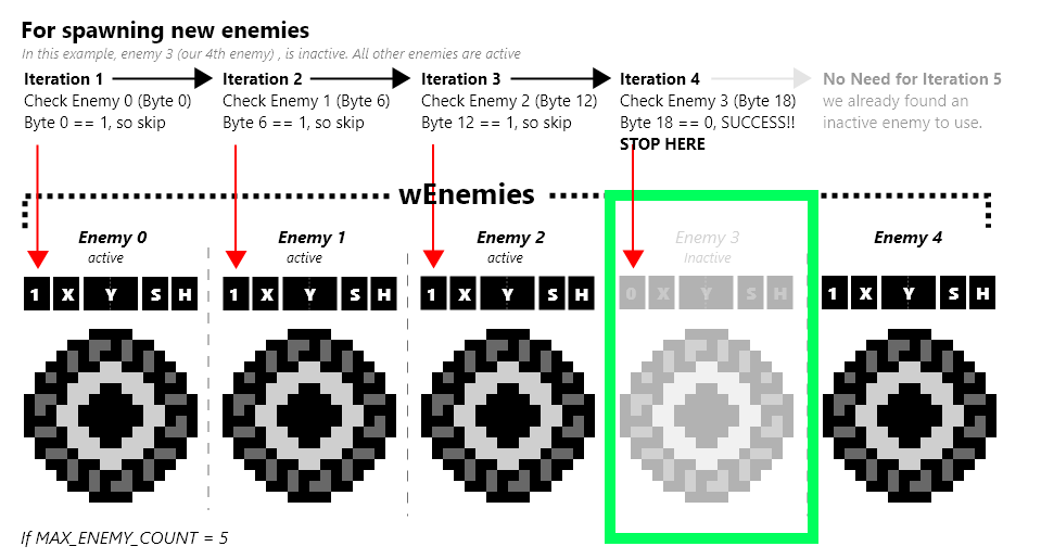
The Player
The player’s logic is pretty simple. The player can move in 4 directions and fire bullets. We update the player by checking our input directions and the A button. We’ll move in the proper direction if its associated d-pad button is pressed. If the A button is pressed, we’ll spawn a new bullet at the player’s position.
Our player will have 3 variables:
- wePlayerPositionX - a 16-bit scaled integer
- wePlayerPositionY - a 16-bit scaled integer
- wPlayerFlash - a 16-bit integer used when the player gets damaged
⚠️ NOTE: The player can move vertically AND horizontally. So, unlike bullets and enemies, it’s x position is a 16-bit scaled integer.
These are declared at the top of the “src/main/states/gameplay/objects/player.asm” file
include "src/main/utils/hardware.inc"
include "src/main/utils/hardware.inc"
include "src/main/utils/constants.inc"
SECTION "PlayerVariables", WRAM0
; first byte is low, second is high (little endian)
wPlayerPositionX:: dw
wPlayerPositionY:: dw
mPlayerFlash: dw
Well draw our player, a simple ship, using the previously discussed metasprites implementation. Here is what we have for the players metasprites and tile data:
SECTION "Player", ROM0
playerShipTileData: INCBIN "src/generated/sprites/player-ship.2bpp"
playerShipTileDataEnd:
playerTestMetaSprite::
.metasprite1 db 0,0,0,0
.metasprite2 db 0,8,2,0
.metaspriteEnd db 128
Initializing the Player
Initializing the player is pretty simple. Here’s a list of things we need to do:
- Reset oir wPlayerFlash variable
- Reset our wPlayerPositionX variable
- Reset our wPlayerPositionU variable
- Copy the player’s ship into VRAM
We’ll use a constant we declared in “src/main/utils/constants.inc” to copy the player ship’s tile data into VRAM. Our enemy ship and player ship both have 4 tiles (16 bytes for each tile). In the snippet below, we can define where we’ll place the tile data in VRAM relative to the _VRAM constant:
RSRESET
DEF spriteTilesStart RB _VRAM
DEF PLAYER_TILES_START RB 4*16
DEF ENEMY_TILES_START RB 4*16
DEF BULLET_TILES_START RB 0
Here’s what our “InitializePlayer” function looks like. Recall, this was called when initiating the gameplay game state:
InitializePlayer::
xor a
ld [mPlayerFlash], a
ld [mPlayerFlash+1], a
; Place in the middle of the screen
xor a
ld [wPlayerPositionX], a
ld [wPlayerPositionY], a
ld a, 5
ld [wPlayerPositionX+1], a
ld [wPlayerPositionY+1], a
CopyPlayerTileDataIntoVRAM:
; Copy the player's tile data into VRAM
ld de, playerShipTileData
ld hl, PLAYER_TILES_START
ld bc, playerShipTileDataEnd - playerShipTileData
call CopyDEintoMemoryAtHL
ret
Updating the Player
We can break our player’s update logic into 2 parts:
- Check for joypad input, move with the d-pad, shoot with A
- Depending on our “wPlayerFlash” variable: Draw our metasprites at our location
Checking the joypad is done like the previous tutorials, we’ll perform bitwise “and” operations with constants for each d-pad direction.
UpdatePlayer::
UpdatePlayer_HandleInput:
ld a, [wCurKeys]
and PADF_UP
call nz, MoveUp
ld a, [wCurKeys]
and PADF_DOWN
call nz, MoveDown
ld a, [wCurKeys]
and PADF_LEFT
call nz, MoveLeft
ld a, [wCurKeys]
and PADF_RIGHT
call nz, MoveRight
ld a, [wCurKeys]
and PADF_A
call nz, TryShoot
For player movement, our X & Y are 16-bit integers. These both require two bytes. There is a little endian ordering, the first byte will be the low byte. The second byte will be the high byte. To increase/decrease these values, we add/subtract our change amount to/from the low byte. Then afterwards, we add/subtract the remainder of that operation to/from the high byte.
MoveUp:
; decrease the player's y position
ld a, [wPlayerPositionY]
sub PLAYER_MOVE_SPEED
ld [wPlayerPositionY], a
ld a, [wPlayerPositionY]
sbc 0
ld [wPlayerPositionY], a
ret
MoveDown:
; increase the player's y position
ld a, [wPlayerPositionY]
add PLAYER_MOVE_SPEED
ld [wPlayerPositionY], a
ld a, [wPlayerPositionY+1]
adc 0
ld [wPlayerPositionY+1], a
ret
MoveLeft:
; decrease the player's x position
ld a, [wPlayerPositionX]
sub PLAYER_MOVE_SPEED
ld [wPlayerPositionX], a
ld a, [wPlayerPositionX+1]
sbc 0
ld [wPlayerPositionX+1], a
ret
MoveRight:
; increase the player's x position
ld a, [wPlayerPositionX]
add PLAYER_MOVE_SPEED
ld [wPlayerPositionX], a
ld a, [wPlayerPositionX+1]
adc 0
ld [wPlayerPositionX+1], a
ret
When the player wants to shoot, we first check if the A button previously was down. If it was, we won’t shoot a new bullet. This avoids bullet spamming a little. For spawning bullets, we have a function called “FireNextBullet”. This function will need the new bullet’s 8-bit X coordinate and 16-bit Y coordinate, both set in a variable it uses called “wNextBullet”
TryShoot:
ld a, [wLastKeys]
and PADF_A
ret nz
jp FireNextBullet
After we’ve potentially moved the player and/or shot a new bullet. We need to draw our player. However, to create the “flashing” effect when damaged, we’ll conditionally NOT draw our player sprite. We do this based on the “wPlayerFlash” variable.
- If the “wPlayerFlash” variable is 0, the player is not damaged, we’ll skip to drawing our player sprite.
- Otherwise, decrease the “wPlayerFlash” variable by 5.
- We’ll shift all the bits of the “wPlayerFlash” variable to the right 4 times
- If the result is less than 5, we’ll stop flashing and draw our player metasprite.
- Otherwise, if the first bit of the decscaled “wPlayerFLash” variable is 1, we’ll skip drawing the player.
*NOTE: The following resumes from where the “UpdatePlayer_HandleInput” label ended above.
ld a, [mPlayerFlash+0]
ld b, a
ld a, [mPlayerFlash+1]
ld c, a
UpdatePlayer_UpdateSprite_CheckFlashing:
ld a, b
or c
jp z, UpdatePlayer_UpdateSprite
; decrease bc by 5
ld a, b
sub 5
ld b, a
ld a, c
sbc 0
ld c, a
UpdatePlayer_UpdateSprite_DecreaseFlashing:
ld a, b
ld [mPlayerFlash], a
ld a, c
ld [mPlayerFlash+1], a
; descale bc
srl c
rr b
srl c
rr b
srl c
rr b
srl c
rr b
ld a, b
cp 5
jp c, UpdatePlayer_UpdateSprite_StopFlashing
bit 0, b
jp z, UpdatePlayer_UpdateSprite
UpdatePlayer_UpdateSprite_Flashing:
ret
UpdatePlayer_UpdateSprite_StopFlashing:
xor a
ld [mPlayerFlash],a
ld [mPlayerFlash+1],a
If we get past all of the “wPlayerFlash” logic, we’ll draw our player using the “DrawMetasprite” function we previously discussed.
UpdatePlayer_UpdateSprite:
; Get the unscaled player x position in b
ld a, [wPlayerPositionX+0]
ld b, a
ld a, [wPlayerPositionX+1]
ld d, a
srl d
rr b
srl d
rr b
srl d
rr b
srl d
rr b
; Get the unscaled player y position in c
ld a, [wPlayerPositionY+0]
ld c, a
ld a, [wPlayerPositionY+1]
ld e, a
srl e
rr c
srl e
rr c
srl e
rr c
srl e
rr c
;;;;;;;;;;;;;;;;;;;;;;;;;;;;;;;;;;;;;;;;;;;;;;;;;;;;;;;;;;;;;;;;;;;;
; Drawing the palyer metasprite
;;;;;;;;;;;;;;;;;;;;;;;;;;;;;;;;;;;;;;;;;;;;;;;;;;;;;;;;;;;;;;;;;;;;
; Save the address of the metasprite into the 'wMetaspriteAddress' variable
; Our DrawMetasprites functoin uses that variable
ld a, LOW(playerTestMetaSprite)
ld [wMetaspriteAddress+0], a
ld a, HIGH(playerTestMetaSprite)
ld [wMetaspriteAddress+1], a
; Save the x position
ld a, b
ld [wMetaspriteX], a
; Save the y position
ld a, c
ld [wMetaspriteY], a
; Actually call the 'DrawMetasprites function
call DrawMetasprites;
;;;;;;;;;;;;;;;;;;;;;;;;;;;;;;;;;;;;;;;;;;;;;;;;;;;;;;;;;;;;;;;;;;;;
;;;;;;;;;;;;;;;;;;;;;;;;;;;;;;;;;;;;;;;;;;;;;;;;;;;;;;;;;;;;;;;;;;;;
;;;;;;;;;;;;;;;;;;;;;;;;;;;;;;;;;;;;;;;;;;;;;;;;;;;;;;;;;;;;;;;;;;;;
ret
That’s the end our our “UpdatePlayer” function. The final bit of code for our player handles when they are damaged. When an enemy damages the player, we want to decrease our lives by one. We’ll also start flashing by giving our ‘mPlayerFlash’ variable a non-zero value. In the gameplay game state, if we’ve lost all lives, gameplay will end.
DamagePlayer::
xor a
ld [mPlayerFlash], a
inc a
ld [mPlayerFlash+1], a
ld a, [wLives]
dec a
ld [wLives], a
ret
That’s everything for our player. Next, we’ll go over bullets and then onto the enemies.
Bullets
Bullets are relatively simple, logic-wise. They all travel straight-forward, and de-activate themselves when they leave the screen.
At the top of our “src/main/states/gameplay/objects/bullets.asm” file we’ll setup some variables for bullets and include our tile data.
include "src/main/utils/hardware.inc"
include "src/main/utils/constants.inc"
SECTION "BulletVariables", WRAM0
wSpawnBullet: db
; how many bullets are currently active
wActiveBulletCounter:: db
; how many bullet's we've updated
wUpdateBulletsCounter: db
; Bytes: active, x , y (low), y (high)
wBullets:: ds MAX_BULLET_COUNT*PER_BULLET_BYTES_COUNT
SECTION "Bullets", ROM0
bulletMetasprite::
.metasprite1 db 0,0,8,0
.metaspriteEnd db 128
bulletTileData:: INCBIN "src/generated/sprites/bullet.2bpp"
bulletTileDataEnd::
We’ll need to loop through the bullet object pool in the following sections.
Initiating Bullets
In our “InitializeBullets” function, we’ll copy the tile data for the bullet sprites into VRAM, and set every bullet as inactive. Each bullet is 4 bytes, the first byte signaling if the bullet is active or not.
We’ll iterate through bullet object pool, named “wBullets”, and activate the first of the the four bytes. Then skipping the next 3 bytes, to go onto the next bullet. We’ll do this until we’ve looped for each bullet in our pool.
InitializeBullets::
xor a
ld [wSpawnBullet], a
; Copy the bullet tile data intto vram
ld de, bulletTileData
ld hl, BULLET_TILES_START
ld bc, bulletTileDataEnd - bulletTileData
call CopyDEintoMemoryAtHL
; Reset how many bullets are active to 0
xor a
ld [wActiveBulletCounter],a
ld b, a
ld hl, wBullets
ld [hl], a
InitializeBullets_Loop:
; Increase the address
ld a, l
add PER_BULLET_BYTES_COUNT
ld l, a
ld a, h
adc 0
ld h, a
; Increase how many bullets we have initailized
ld a, b
inc a
ld b, a
cp MAX_BULLET_COUNT
ret z
jp InitializeBullets_Loop
Updating Bullets
When we want to update each of bullets, first we should check if any bullets are active. If no bullets are active we can stop early.
UpdateBullets::
; Make sure we have SOME active enemies
ld a, [wSpawnBullet]
ld b, a
ld a, [wActiveBulletCounter]
or b
cp 0
ret z
; Reset our counter for how many bullets we have checked
xor a
ld [wUpdateBulletsCounter], a
; Get the address of the first bullet in hl
ld a, LOW(wBullets)
ld l, a
ld a, HIGH(wBullets)
ld h, a
jp UpdateBullets_PerBullet
If we have active bullets, we’ll reset how many bullets we’ve checked and set our “hl” registers to point to the first bullets address.
When were updating each bullet, we’ll check each byte, changing hl (the byte we want to read) as we go. At the start, “hl” should point to the first byte. “hl” should point to the first byte at the end too:
HL should point to the first byte at the end so we can easily do one of two things:
- deactivate the bullet
- jump to the next bullet (by simply adding 4 to hl)
For we each bullet, we’ll do the following:
- Check if active
- Get our x position, save into b
- Get our y scaled positon, save into c (low byte), and d (high byte)
- Decrease our y position to move the bullet upwards
- Reset HL to the first byte of our bullet
- Descale the y position we have in c & d, and jump to our deactivation code if c (the low byte) is high enough
- Draw our bullet metasprit, if it wasn’t previously deactivated
UpdateBullets_PerBullet:
; The first byte is if the bullet is active
; If it's NOT zero, it's active, go to the normal update section
ld a, [hl]
and a
jp nz, UpdateBullets_PerBullet_Normal
; Do we need to spawn a bullet?
; If we dont, loop to the next enemy
ld a, [wSpawnBullet]
and a
jp z, UpdateBullets_Loop
UpdateBullets_PerBullet_SpawnDeactivatedBullet:
; reset this variable so we don't spawn anymore
xor a
ld [wSpawnBullet], a
; Increase how many bullets are active
ld a, [wActiveBulletCounter]
inc a
ld [wActiveBulletCounter], a
push hl
; Set the current bullet as active
ld a, 1
ld [hli], a
; Get the unscaled player x position in b
ld a, [wPlayerPositionX]
ld b, a
ld a, [wPlayerPositionX+1]
ld d, a
; Descale the player's x position
; the result will only be in the low byt
srl d
rr b
srl d
rr b
srl d
rr b
srl d
rr b
; Set the x position to equal the player's x position
ld a, b
ld [hli], a
; Set the y position (low)
ld a, [wPlayerPositionY]
ld [hli], a
; Set the y position (high)
ld a, [wPlayerPositionY+1]
ld [hli], a
pop hl
UpdateBullets_PerBullet_Normal:
; Save our active byte
push hl
inc hl
; Get our x position
ld a, [hli]
ld b, a
; get our 16-bit y position
ld a, [hl]
sub BULLET_MOVE_SPEED
ld [hli], a
ld c, a
ld a, [hl]
sbc 0
ld [hl], a
ld d, a
pop hl; go to the active byte
; Descale our y position
srl d
rr c
srl d
rr c
srl d
rr c
srl d
rr c
; See if our non scaled low byte is above 160
ld a, c
cp 178
; If it's below 160, deactivate
jp nc, UpdateBullets_DeActivateIfOutOfBounds
Drawing the Bullets
We’ll draw our bullet metasprite like we drew the player, using our “DrawMetasprites” function. This function may alter the ‘h’ or ‘l’ registers, so we’ll push the hl register onto the stack before hand. After drawing, we’ll pop the hl register off of the stack to restore it’s value.
push hl
;;;;;;;;;;;;;;;;;;;;;;;;;;;;;;;;;;;;;;;;;;;;;;;;;;;;;;;;;;;;;;;;;;;;;;;;;;;;;;;;;;;;;;;;
;; Drawing a metasprite
;;;;;;;;;;;;;;;;;;;;;;;;;;;;;;;;;;;;;;;;;;;;;;;;;;;;;;;;;;;;;;;;;;;;;;;;;;;;;;;;;;;;;;;;
; Save the address of the metasprite into the 'wMetaspriteAddress' variable
; Our DrawMetasprites functoin uses that variable
ld a, LOW(bulletMetasprite)
ld [wMetaspriteAddress], a
ld a, HIGH(bulletMetasprite)
ld [wMetaspriteAddress+1], a
; Save the x position
ld a, b
ld [wMetaspriteX], a
; Save the y position
ld a, c
ld [wMetaspriteY], a
; Actually call the 'DrawMetasprites function
call DrawMetasprites
;;;;;;;;;;;;;;;;;;;;;;;;;;;;;;;;;;;;;;;;;;;;;;;;;;;;;;;;;;;;;;;;;;;;;;;;;;;;;;;;;;;;;;;;
;;;;;;;;;;;;;;;;;;;;;;;;;;;;;;;;;;;;;;;;;;;;;;;;;;;;;;;;;;;;;;;;;;;;;;;;;;;;;;;;;;;;;;;;
pop hl
jp UpdateBullets_Loop
Deactivating the Bullets
If a bullet needs to be deactivated, we simply set it’s first byte to 0. At this point in time, the “hl” registers should point at our bullets first byte. This makes deactivation a really simple task. In addition to changing the first byte, we’ll decrease how many bullets we have that are active.
UpdateBullets_DeActivateIfOutOfBounds:
; if it's y value is grater than 160
; Set as inactive
xor a
ld [hl], a
; Decrease counter
ld a,[wActiveBulletCounter]
dec a
ld [wActiveBulletCounter], a
jp UpdateBullets_Loop
Updating the next bullet
After we’ve updated a single bullet, we’ll increase how many bullet’s we’ve updated. If we’ve updated all the bullets, we can stop our “UpdateBullets” function. Otherwise, we’ll add 4 bytes to the addressed stored in “hl”, and update the next bullet.
UpdateBullets_Loop:
; Check our counter, if it's zero
; Stop the function
ld a, [wUpdateBulletsCounter]
inc a
ld [wUpdateBulletsCounter], a
; Check if we've already
ld a, [wUpdateBulletsCounter]
cp MAX_BULLET_COUNT
ret nc
; Increase the bullet data our address is pointingtwo
ld a, l
add PER_BULLET_BYTES_COUNT
ld l, a
ld a, h
adc 0
ld h, a
Firing New Bullets
During the “UpdatePlayer” function previously, when use pressed A we called the “FireNextBullet” function.
This function will loop through each bullet in the bullet object pool. When it finds an inactive bullet, it will activate it and set it’s position equal to the players.
Our bullets only use one 8-bit integer for their x position, so need to de-scale the player’s 16-bit scaled x position
FireNextBullet::
; Make sure we don't have the max amount of enmies
ld a, [wActiveBulletCounter]
cp MAX_BULLET_COUNT
ret nc
; Set our spawn bullet variable to true
ld a, 1
ld [wSpawnBullet], a
ret
That’s it for bullets logic. Next we’ll cover enemies, and after that we’ll step back into the world of bullets with “Bullet vs Enemy” Collision.
Enemies
Enemies in SHMUPS often come in a variety of types, and travel also in a variety of patterns. To keep things simple for this tutorial, we’ll have one enemy that flys straight downward. Because of this decision, the logic for enemies is going to be similar to bullets in a way. They both travel vertically and disappear when off screeen. Some differences to point out are:
- Enemies are not spawned by the player, so we need logic that spawns them at random times and locations.
- Enemies must check for collision against the player
- We’ll check for collision against bullets in the enemy update function.
Here are the RAM variables we’ll use for our enemies:
- wCurrentEnemyX & wCurrentEnemyY - When we check for collisions, we’ll save the current enemy’s position in these two variables.
- wNextEnemyXPosition - When this variable has a non-zero value, we’ll spawn a new enemy at that position
- wSpawnCounter - We’ll decrease this, when it reaches zero we’ll spawn a new enemy (by setting ‘wNextEnemyXPosition’ to a non-zero value).
- wActiveEnemyCounter - This tracks how many enemies we have on screen
- wUpdateEnemiesCounter - This is used when updating enemies so we know how many we have updated.
- wUpdateEnemiesCurrentEnemyAddress - When we check for enemy v. bullet collision, we’ll save the address of our current enemy here.
include "src/main/utils/hardware.inc"
include "src/main/utils/constants.inc"
SECTION "EnemyVariables", WRAM0
wCurrentEnemyX:: db
wCurrentEnemyY:: db
wSpawnCounter: db
wNextEnemyXPosition: db
wActiveEnemyCounter::db
wUpdateEnemiesCounter:db
wUpdateEnemiesCurrentEnemyAddress::dw
; Bytes: active, x , y (low), y (high), speed, health
wEnemies:: ds MAX_ENEMY_COUNT*PER_ENEMY_BYTES_COUNT
Just like with bullets, we’ll setup ROM data for our enemies tile data and metasprites.
SECTION "Enemies", ROM0
enemyShipTileData:: INCBIN "src/generated/sprites/enemy-ship.2bpp"
enemyShipTileDataEnd::
enemyShipMetasprite::
.metasprite1 db 0,0,4,0
.metasprite2 db 0,8,6,0
.metaspriteEnd db 128
Initializing Enemies
When initializing the enemies (at the start of gameplay), we’ll copy the enemy tile data into VRAM. Also, like with bullets, we’ll loop through and make sure each enemy is set to inactive.
InitializeEnemies::
ld de, enemyShipTileData
ld hl, ENEMY_TILES_START
ld bc, enemyShipTileDataEnd - enemyShipTileData
call CopyDEintoMemoryAtHL
xor a
ld [wSpawnCounter], a
ld [wActiveEnemyCounter], a
ld [wNextEnemyXPosition], a
ld b, a
ld hl, wEnemies
InitializeEnemies_Loop:
; Set as inactive
ld [hl], 0
; Increase the address
ld a, l
add PER_ENEMY_BYTES_COUNT
ld l, a
ld a, h
adc 0
ld h, a
inc b
ld a, b
cp MAX_ENEMY_COUNT
ret z
jp InitializeEnemies_Loop
Updating Enemies
When “UpdateEnemies” is called from gameplay, the first thing we try to do is spawn new enemies. After that, if we have no active enemies (and are not trying to spawn a new enemy), we stop the “UpdateEnemies” function. From here, like with bullets, we’ll save the address of our first enemy in hl and start looping through.
UpdateEnemies::
call TryToSpawnEnemies
; Make sure we have active enemies
; or we want to spawn a new enemy
ld a, [wNextEnemyXPosition]
ld b, a
ld a, [wActiveEnemyCounter]
or b
and a
ret z
xor a
ld [wUpdateEnemiesCounter], a
ld a, LOW(wEnemies)
ld l, a
ld a, HIGH(wEnemies)
ld h, a
jp UpdateEnemies_PerEnemy
When we are looping through our enemy object pool, let’s check if the current enemy is active. If it’s active, we’ll update it like normal. If it isn’t active, the game checks if we want to spawn a new enemy. We specify we want to spawn a new enemy by setting ‘wNextEnemyXPosition’ to a non-zero value. If we don’t want to spawn a new enemy, we’ll move on to the next enemy.
If we want to spawn a new enemy, we’ll set the current inactive enemy to active. Afterwards, we’ll set it’s y position to zero, and it’s x position to whatever was in the ‘wNextEnemyXPosition’ variable. After that, we’ll increase our active enemy counter, and go on to update the enemy like normal.
UpdateEnemies_PerEnemy:
; The first byte is if the current object is active
; If it's not zero, it's active, go to the normal update section
ld a, [hl]
and a
jp nz, UpdateEnemies_PerEnemy_Update
UpdateEnemies_SpawnNewEnemy:
; If this enemy is NOT active
; Check If we want to spawn a new enemy
ld a, [wNextEnemyXPosition]
and a
; If we don't want to spawn a new enemy, we'll skip this (deactivated) enemy
jp z, UpdateEnemies_Loop
push hl
; If they are deactivated, and we want to spawn an enemy
; activate the enemy
ld a, 1
ld [hli], a
; Put the value for our enemies x position
ld a, [wNextEnemyXPosition]
ld [hli], a
; Put the value for our enemies y position to equal 0
xor a
ld [hli], a
ld [hld], a
ld [wNextEnemyXPosition], a
pop hl
; Increase counter
ld a, [wActiveEnemyCounter]
inc a
ld [wActiveEnemyCounter], a
When We are done updating a single enemy, we’ll jump to the “UpdateEnemies_Loop” label. Here we’ll increase how many enemies we’ve updated, and end if we’ve done them all. If we still have more enemies left, we’ll increase the address stored in hl by 6 and update the next enemy.
The “hl” registers should always point to the current enemies first byte when this label is reached.
UpdateEnemies_Loop:
; Check our coutner, if it's zero
; Stop the function
ld a, [wUpdateEnemiesCounter]
inc a
ld [wUpdateEnemiesCounter], a
; Compare against the active count
cp MAX_ENEMY_COUNT
ret nc
; Increase the enemy data our address is pointingtwo
ld a, l
add PER_ENEMY_BYTES_COUNT
ld l, a
ld a, h
adc 0
ld h, a
For updating enemies, we’ll first get the enemies speed. Afterwards we’ll increase the enemies 16-bit y position. Once we’ve done that, we’ll descale the y position so we can check for collisions and draw the ennemy.
UpdateEnemies_PerEnemy_Update:
; Save our first bytye
push hl
; Get our move speed in e
ld bc, enemy_speedByte
add hl, bc
ld a, [hl]
ld e, a
; Go back to the first byte
; put the address toe the first byte back on the stack for later
pop hl
push hl
inc hl
; Get our x position
ld a, [hli]
ld b, a
ld [wCurrentEnemyX], a
; get our 16-bit y position
; increase it (by e), but also save it
ld a, [hl]
add 10
ld [hli], a
ld c, a
ld a, [hl]
adc 0
ld [hl], a
ld d, a
pop hl
; Descale the y psoition
srl d
rr c
srl d
rr c
srl d
rr c
srl d
rr c
ld a, c
ld [wCurrentEnemyY], a
Player & Bullet Collision
One of the differences between enemies and bullets is that enemies must check for collision against the player and also against bullets. For both of these cases, we’ll use a simple Axis-Aligned Bounding Box test. We’ll cover the specific logic in a later section.
If we have a collison against the player we need to damage the player, and redraw how many lives they have. In addition, it’s optional, but we’ll deactivate the enemy too when they collide with the player.
Our “hl” registers should point to the active byte of the current enemy. We push and pop our “hl” registers to make sure we get back to that same address for later logic.
UpdateEnemies_PerEnemy_CheckPlayerCollision:
push hl
call CheckCurrentEnemyAgainstBullets
call CheckEnemyPlayerCollision
pop hl
ld a, [wResult]
and a
jp z, UpdateEnemies_NoCollisionWithPlayer
;;;;;;;;;;;;;;;;;;;;;;;;;;;;;;;;;;;;;;;;;;;;;;;;;;;;;;;;;;;;;;;;;;;;;;;;;;;;;;;;;;;
push hl
call DamagePlayer
call DrawLives
pop hl
jp UpdateEnemies_DeActivateEnemy
If there is no collision with the player, we’ll draw the enemies. This is done just as we did the player and bullets, with the “DrawMetasprites” function.
UpdateEnemies_NoCollisionWithPlayer::
; See if our non scaled low byte is above 160
ld a, [wCurrentEnemyY]
cp 160
jp nc, UpdateEnemies_DeActivateEnemy
push hl
;;;;;;;;;;;;;;;;;;;;;;;;;;;;;;;;;;;;;;;;;;;;;;;;;;;;;;;;;;;;;;;;;;;;;;;;;;;;;;;;;;;;;;;
; call the 'DrawMetasprites function. setup variables and call
;;;;;;;;;;;;;;;;;;;;;;;;;;;;;;;;;;;;;;;;;;;;;;;;;;;;;;;;;;;;;;;;;;;;;;;;;;;;;;;;;;;;;;;;;;;;;
; Save the address of the metasprite into the 'wMetaspriteAddress' variable
; Our DrawMetasprites functoin uses that variable
ld a, LOW(enemyShipMetasprite)
ld [wMetaspriteAddress+0], a
ld a, HIGH(enemyShipMetasprite)
ld [wMetaspriteAddress+1], a
; Save the x position
ld a, [wCurrentEnemyX]
ld [wMetaspriteX], a
; Save the y position
ld a, [wCurrentEnemyY]
ld [wMetaspriteY], a
; Actually call the 'DrawMetasprites function
call DrawMetasprites
;;;;;;;;;;;;;;;;;;;;;;;;;;;;;;;;;;;;;;;;;;;;;;;;;;;;;;;;;;;;;;;;;;;;;;;;;;;;;;;;;;;;;;;;;;;;;
;;;;;;;;;;;;;;;;;;;;;;;;;;;;;;;;;;;;;;;;;;;;;;;;;;;;;;;;;;;;;;;;;;;;;;;;;;;;;;;;;;;;;;;;;;;;;
;;;;;;;;;;;;;;;;;;;;;;;;;;;;;;;;;;;;;;;;;;;;;;;;;;;;;;;;;;;;;;;;;;;;;;;;;;;;;;;;;;;;;;;;;;;;;
pop hl
jp UpdateEnemies_Loop
Deactivating Enemies
Deactivating an enemy is just like with bullets. We’ll set it’s first byte to 0, and decrease our counter variable.
Here, we can just use the current address in HL. This is the second reason we wanted to keep the address of our first byte on the stack.
UpdateEnemies_DeActivateEnemy:
; Set as inactive
xor a
ld [hl], a
; Decrease counter
ld a, [wActiveEnemyCounter]
dec a
ld [wActiveEnemyCounter], a
jp UpdateEnemies_Loop
Spawning Enemies
Randomly, we want to spawn enemies. We’ll increase a counter called “wEnemyCounter”. When it reaches a preset maximum value, we’ll maybe try to spawn a new enemy.
Firstly, We need to make sure we aren’t at maximum enemy capacity, if so, we will not spawn enemy more enemies. If we are not at maximum capacity, we’ll try to get a x position to spawn the enemy at. If our x position is below 24 or above 150, we’ll also NOT spawn a new enemy.
All enemies are spawned with y position of 0, so we only need to get the x position.
If we have a valid x position, we’ll reset our spawn counter, and save that x position in the “wNextEnemyXPosition” variable. With this variable set, We’ll later activate and update a enemy that we find in the inactive state.
TryToSpawnEnemies::
; Increase our spwncounter
ld a, [wSpawnCounter]
inc a
ld [wSpawnCounter], a
; Check our spawn acounter
; Stop if it's below a given value
ld a, [wSpawnCounter]
cp ENEMY_SPAWN_DELAY_MAX
ret c
; Check our next enemy x position variable
; Stop if it's non zero
ld a, [wNextEnemyXPosition]
cp 0
ret nz
; Make sure we don't have the max amount of enmies
ld a, [wActiveEnemyCounter]
cp MAX_ENEMY_COUNT
ret nc
GetSpawnPosition:
; Generate a semi random value
call rand
; make sure it's not above 150
ld a, b
cp 150
ret nc
; make sure it's not below 24
ld a, b
cp 24
ret c
; reset our spawn counter
xor a
ld [wSpawnCounter], a
ld a, b
ld [wNextEnemyXPosition], a
ret
Collision Detection
Collision Detection is cruical to games. It can be a very complicated topic. In Galactic Armada, things will be kept super simple. We’re going to perform a basic implementation of “Axis-Aligned Bounding Box Collision Detection”:
One of the simpler forms of collision detection is between two rectangles that are axis aligned — meaning no rotation. The algorithm works by ensuring there is no gap between any of the 4 sides of the rectangles. Any gap means a collision does not exist.1
The easiest way to check for overlap, is to check the difference bewteen their centers. If the absolute value of their x & y differences (I’ll refer to as “the absolute difference”) are BOTH smaller than the sum of their half widths, we have a collision. This collision detection is run for bullets against enemies, and enemies against the player. Here’s a visualization with bullets and enemies.
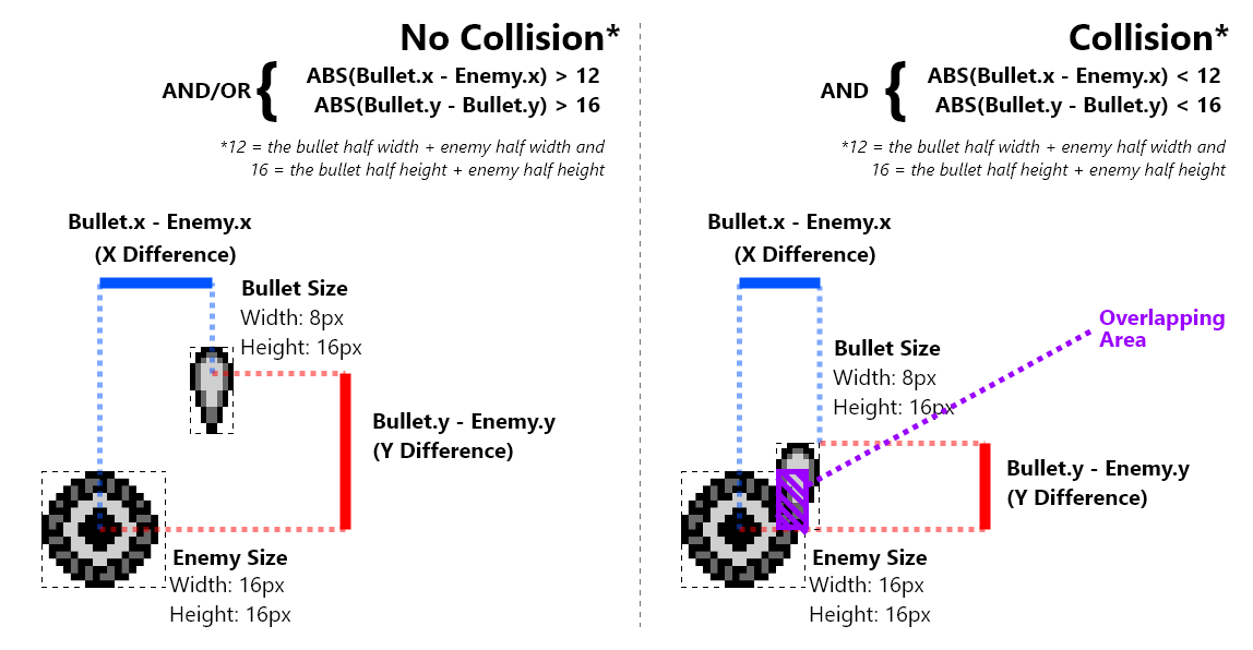
For this, we’ve created a basic function called “CheckObjectPositionDifference”. This function will help us check for overlap on the x or y axis. When the (absolute) difference between the first two values passed is greater than the third value passed, it jump’s to the label passed in the fourth parameter.
Here’s an example of how to call this function:
We have the player’s Y position in the
dregister. We’ll check it’s value against the y value of the current enemy, which we have in a variable namedwCurrentEnemyY.
;;;;;;;;;;;;;;;;;;;;;;;;;;;;;;;;;;;;;;;;;;;;;;;;;;;;;;;;;;;;;;;;;;;;;;;;;;;;;;;;;;;
; Check the y distances. Jump to 'NoCollisionWithPlayer' on failure
;;;;;;;;;;;;;;;;;;;;;;;;;;;;;;;;;;;;;;;;;;;;;;;;;;;;;;;;;;;;;;;;;;;;;;;;;;;;;;;;;;;
ld a, [wCurrentEnemyY]
ld [wObject1Value], a
ld a, d
ld [wObject2Value], a
; Save if the minimum distance
ld a, 16
ld [wSize], a
call CheckObjectPositionDifference
ld a, [wResult]
and a
jp z, NoCollisionWithPlayer
;;;;;;;;;;;;;;;;;;;;;;;;;;;;;;;;;;;;;;;;;;;;;;;;;;;;;;;;;;;;;;;;;;;;;;;;;;;;;;;;;;;
When checking for collision, we’ll use that function twice. Once for the x-axis, and again for the y-axis.
NOTE: We don’t need to test the y-axis if the x-axis fails.
The source code for that function looks like this:
include "src/main/utils/constants.inc"
include "src/main/utils/hardware.inc"
SECTION "CollisionUtilsVariables", WRAM0
wResult:: db
wSize:: db
wObject1Value:: db
wObject2Value:: db
SECTION "CollisionUtils", ROM0
CheckObjectPositionDifference::
; at this point in time; e = enemy.y, b =bullet.y
ld a, [wObject1Value]
ld e, a
ld a, [wObject2Value]
ld b, a
ld a, [wSize]
ld d, a
; subtract bullet.y, (aka b) - (enemy.y+8, aka e)
; carry means e<b, means enemy.bottom is visually above bullet.y (no collision)
ld a, e
add d
cp b
; carry means no collision
jp c, CheckObjectPositionDifference_Failure
; subtract enemy.y-8 (aka e) - bullet.y (aka b)
; no carry means e>b, means enemy.top is visually below bullet.y (no collision)
ld a, e
sub d
cp b
; no carry means no collision
jp nc, CheckObjectPositionDifference_Failure
ld a, 1
ld [wResult], a
ret
CheckObjectPositionDifference_Failure:
ld a,0
ld [wResult], a
ret;
Enemy-Player Collision
Our enemy versus player collision detection starts with us getting our player’s unscaled x position. We’ll store that value in d.
CheckEnemyPlayerCollision::
; Get our player's unscaled x position in d
ld a, [wPlayerPositionX]
ld d, a
ld a, [wPlayerPositionX+1]
ld e, a
srl e
rr d
srl e
rr d
srl e
rr d
srl e
rr d
With our player’s x position in d, we’ll compare it against a previously saved enemy x position variable. If they are more than 16 pixels apart, we’ll jump to the “NoCollisionWithPlayer” label.
;;;;;;;;;;;;;;;;;;;;;;;;;;;;;;;;;;;;;;;;;;;;;;;;;;;;;;;;;;;;;;;;;;;;;;;;;;;;;;;;;;;
; Check the x distances. Jump to 'NoCollisionWithPlayer' on failure
;;;;;;;;;;;;;;;;;;;;;;;;;;;;;;;;;;;;;;;;;;;;;;;;;;;;;;;;;;;;;;;;;;;;;;;;;;;;;;;;;;;
ld a, [wCurrentEnemyX]
ld [wObject1Value], a
ld a, d
ld [wObject2Value], a
; Save if the minimum distance
ld a, 16
ld [wSize], a
call CheckObjectPositionDifference
ld a, [wResult]
and a
jp z, NoCollisionWithPlayer
;;;;;;;;;;;;;;;;;;;;;;;;;;;;;;;;;;;;;;;;;;;;;;;;;;;;;;;;;;;;;;;;;;;;;;;;;;;;;;;;;;;
After checking the x axis, if the code gets this far there was an overlap. We’ll do the same for the y axis next.
We’ll get the player’s unscaled y position. We’ll store that value in d for consistency.
; Get our player's unscaled y position in d
ld a, [wPlayerPositionY+0]
ld d, a
ld a, [wPlayerPositionY+1]
ld e, a
srl e
rr d
srl e
rr d
srl e
rr d
srl e
rr d
Just like before, we’ll compare our player’s unscaled y position (stored in d) against a previously saved enemy y position variable. If they are more than 16 pixels apart, we’ll jump to the “NoCollisionWithPlayer” label.
;;;;;;;;;;;;;;;;;;;;;;;;;;;;;;;;;;;;;;;;;;;;;;;;;;;;;;;;;;;;;;;;;;;;;;;;;;;;;;;;;;;
; Check the y distances. Jump to 'NoCollisionWithPlayer' on failure
;;;;;;;;;;;;;;;;;;;;;;;;;;;;;;;;;;;;;;;;;;;;;;;;;;;;;;;;;;;;;;;;;;;;;;;;;;;;;;;;;;;
ld a, [wCurrentEnemyY]
ld [wObject1Value], a
ld a, d
ld [wObject2Value], a
; Save if the minimum distance
ld a, 16
ld [wSize], a
call CheckObjectPositionDifference
ld a, [wResult]
and a
jp z, NoCollisionWithPlayer
;;;;;;;;;;;;;;;;;;;;;;;;;;;;;;;;;;;;;;;;;;;;;;;;;;;;;;;;;;;;;;;;;;;;;;;;;;;;;;;;;;;
The “NoCollisionWithPlayer”, just set’s the “wResult” to 0 for failure. If overlap occurs on both axis, we’ll isntead set 1 for success.
ld a, 1
ld [wResult], a
ret
NoCollisionWithPlayer::
xor a
ld [wResult], a
ret
That’s the enemy-player collision logic. Callers of the function can simply check the “wResult” variable to determine if there was collision.
Enemy-Bullet Collision
When we are udating enemies, we’ll call a function called “CheckCurrentEnemyAgainstBullets”. This will check the current enemy against all active bullets.
This fuction needs to loop through the bullet object pool, and check if our current enemy overlaps any bullet on both the x and y axis. If so, we’ll deactivate the enemy and bullet.
Our “CheckCurrentEnemyAgainstBullets” function starts off in a manner similar to how we updated enemies & bullets.
This function expects “hl” points to the curent enemy. We’ll save that in a variable for later usage.
include "src/main/utils/hardware.inc"
include "src/main/utils/constants.inc"
include "src/main/utils/hardware.inc"
SECTION "EnemyBulletCollisionVariables", WRAM0
wEnemyBulletCollisionCounter: db
wBulletAddresses: dw
SECTION "EnemyBulletCollision", ROM0
; called from enemies.asm
CheckCurrentEnemyAgainstBullets::
ld a, l
ld [wUpdateEnemiesCurrentEnemyAddress], a
ld a, h
ld [wUpdateEnemiesCurrentEnemyAddress+1], a
xor a
ld [wEnemyBulletCollisionCounter], a
; Copy our bullets address into wBulletAddress
ld a, LOW(wBullets)
ld l, a
ld a, HIGH(wBullets)
ld h, a
jp CheckCurrentEnemyAgainstBullets_PerBullet
As we loop through the bullets, we need to make sure we only check active bullets. Inactive bullets will be skipped.
CheckCurrentEnemyAgainstBullets_PerBullet:
ld a, [hl]
cp 1
jp nz, CheckCurrentEnemyAgainstBullets_Loop
First, we need to check if the current enemy and current bullet are overlapping on the x axis. We’ll get the enemy’s x position in e, and the bullet’s x position in b. From there, we’ll again call our “CheckObjectPositionDifference” function. If it returns a failure (wResult=0), we’ll start with the next bullet.
We add an offset to the x coordinates so they measure from their centers. That offset is half it’s respective object’s width.
CheckCurrentEnemyAgainstBullets_Check_X_Overlap:
; Save our first byte address
push hl
inc hl
; Get our x position
ld a, [hli]
add 4
ld b, a
push hl
;;;;;;;;;;;;;;;;;;;;;;;;;;;;;;;;;;;;;;;;;;;;;;;;;;;;;;;;;;;;;;;;;;;;;;;;;;;;;;;;;;;;;;;;;;;;;;;;;;;
;; Start: Checking the absolute difference
;;;;;;;;;;;;;;;;;;;;;;;;;;;;;;;;;;;;;;;;;;;;;;;;;;;;;;;;;;;;;;;;;;;;;;;;;;;;;;;;;;;;;;;;;;;;;;;;;;;
; The first value
ld a, b
ld [wObject1Value], a
; The second value
ld a, [wCurrentEnemyX]
add 8
ld [wObject2Value], a
; Save if the minimum distance
ld a, 12
ld [wSize], a
call CheckObjectPositionDifference
ld a, [wResult]
and a
jp z, CheckCurrentEnemyAgainstBullets_Check_X_Overlap_Fail
pop hl
jp CheckCurrentEnemyAgainstBullets_PerBullet_Y_Overlap
CheckCurrentEnemyAgainstBullets_Check_X_Overlap_Fail:
pop hl
pop hl
jp CheckCurrentEnemyAgainstBullets_Loop
Next we restore our hl variable so we can get the y position of our current bullet. Once we have that y position, we’ll get the current enemy’s y position and check for an overlap on the y axis. If no overlap is found, we’ll loop to the next bullet. Otherwise, we have a collision.
CheckCurrentEnemyAgainstBullets_PerBullet_Y_Overlap:
; get our bullet 16-bit y position
ld a, [hli]
ld b, a
ld a, [hli]
ld c, a
; Descale our 16 bit y position
srl c
rr b
srl c
rr b
srl c
rr b
srl c
rr b
; preserve our first byte addresss
pop hl
push hl
;;;;;;;;;;;;;;;;;;;;;;;;;;;;;;;;;;;;;;;;;;;;;;;;;;;;;;;;;;;;;;;;;;;;;;;;;;;;;;;;;;;;;;;;;;;;;;;;;;;
;; Start: Checking the absolute difference
;;;;;;;;;;;;;;;;;;;;;;;;;;;;;;;;;;;;;;;;;;;;;;;;;;;;;;;;;;;;;;;;;;;;;;;;;;;;;;;;;;;;;;;;;;;;;;;;;;;
; The first value
ld a, b
ld [wObject1Value], a
; The second value
ld a, [wCurrentEnemyY]
ld [wObject2Value], a
; Save if the minimum distance
ld a, 16
ld [wSize], a
call CheckObjectPositionDifference
pop hl
ld a, [wResult]
and a
jp z, CheckCurrentEnemyAgainstBullets_Loop
jp CheckCurrentEnemyAgainstBullets_PerBullet_Collision
;;;;;;;;;;;;;;;;;;;;;;;;;;;;;;;;;;;;;;;;;;;;;;;;;;;;;;;;;;;;;;;;;;;;;;;;;;;;;;;;;;;;;;;;;;;;;;;;;;;
;; End: Checking the absolute difference
;;;;;;;;;;;;;;;;;;;;;;;;;;;;;;;;;;;;;;;;;;;;;;;;;;;;;;;;;;;;;;;;;;;;;;;;;;;;;;;;;;;;;;;;;;;;;;;;;;;
If a collision was detected (overlap on x and y axis), we’ll set the current active byte for that bullet to 0. Also , we’ll set the active byte for the current enemy to zero. Before we end the function, we’ll increase and redraw the score, and decrease how many bullets & enemies we have by one.
CheckCurrentEnemyAgainstBullets_PerBullet_Collision:
; set the active byte and x value to 0 for bullets
xor a
ld [hli], a
ld [hl], a
ld a, [wUpdateEnemiesCurrentEnemyAddress+0]
ld l, a
ld a, [wUpdateEnemiesCurrentEnemyAddress+1]
ld h, a
; set the active byte and x value to 0 for enemies
xor a
ld [hli], a
ld [hl], a
call IncreaseScore
call DrawScore
; Decrease how many active enemies their are
ld a, [wActiveEnemyCounter]
dec a
ld [wActiveEnemyCounter], a
; Decrease how many active bullets their are
ld a, [wActiveBulletCounter]
dec a
ld [wActiveBulletCounter], a
ret
If no collision happened, we’ll continue our loop through the enemy bullets. When we’ve checked all the bullets, we’ll end the function.
CheckCurrentEnemyAgainstBullets_Loop:
; increase our counter
ld a, [wEnemyBulletCollisionCounter]
inc a
ld [wEnemyBulletCollisionCounter], a
; Stop if we've checked all bullets
cp MAX_BULLET_COUNT
ret nc
; Increase the data our address is pointing to
ld a, l
add PER_BULLET_BYTES_COUNT
ld l, a
ld a, h
adc 0
ld h, a
Conclusion
If you liked this tutorial, and you want to take things to the next level, here are some ideas:
- Add an options menu (for typewriter speed, difficulty, disable audio)
- Add Ship Select and different player ships
- Add the ability to upgrade your bullet type
- Add dialogue and “waves” of enemies
- Add different types of enemies
- Add a boss
- Add a level select
Where to go next
Oh.
Well, you’ve reached the end of the tutorial… And yes, as you can see, it’s not finished yet.
We’re actively working on new content (and improvement of the existing one).
In the meantime, the best course of action is to peruse the resources in the next section, and experiment by yourself. Well, given that, it may be a good idea to ask around for advice. A lot of the problems and questions you will be encountering have already been solved, so others can—and will!—help you getting started faster.
If you enjoyed the tutorial, please consider contributing, donating to our OpenCollective or simply share the link to this book.
RGBDS Cheatsheet
The purpose of this page is to provide concise explanations and code snippets for common tasks. For extra depth, clarity, and understanding, it’s recommended you read through the Hello World, Part II - Our first game, and Part III - Our second game tutorials.
Assembly syntax & CPU Instructions will not be explained, for more information see the RGBDS Language Reference
Is there something common you think is missing? Check the github repository to open an Issue or contribute to this page. Alternatively, you can reach out on one of the @gbdev community channels.
Table of Contents
Display
The rLCDC register controls all of the following:
- The screen
- The background
- The window
- Sprite objects
For more information on LCD control, refer to the Pan Docs
Wait for the vertical blank phase
To check for the vertical blank phase, use the rLY register. Compare that register’s value against the height of the Game Boy screen in pixels: 144.
WaitUntilVerticalBlankStart:
ldh a, [rLY]
cp 144
jp c, WaitUntilVerticalBlankStart
Turn on/off the LCD
You can turn the LCD on and off by altering the most significant bit of the rLCDC register. hardware.inc a constant for this: LCDCF_ON .
To turn the LCD on:
ld a, LCDCF_ON
ldh [rLCDC], a
To turn the LCD off:
⚠️
Do not turn the LCD off outside of the Vertical Blank Phase. See “Wait for the vertical blank phase”.
; Turn the LCD off
ld a, LCDCF_OFF
ldh [rLCDC], a
Turn on/off the background
To turn the background layer on and off, alter the least significant bit of the rLCDC register. You can use the LCDCF_BGON constant for this.
To turn the background on:
; Turn the background on
ldh a, [rLCDC]
or a, LCDCF_BGON
ldh [rLCDC], a
To turn the background off:
; Turn the background off
ldh a, [rLCDC]
and a, ~LCDCF_BGON
ldh [rLCDC], a
Turn on/off the window
To turn the window layer on and off, alter the least significant bit of the rLCDC register. You can use the LCDCF_WINON and LCDCF_WINOFF constants for this.
To turn the window on:
; Turn the window on
ldh a, [rLCDC]
or a, LCDCF_WINON
ldh [rLCDC], a
To turn the window off:
; Turn the window off
ldh a, [rLCDC]
and a, LCDCF_WINOFF
ldh [rLCDC], a
Switch which tilemaps are used by the window and/or background
By default, the window and background layer will use the same tilemap.
For the window and background, there are 2 memory regions they can use: $9800 and $9C00. For more information, refer to the Pan Docs
Which region the background uses is controlled by the 4th bit of the rLCDC register. Which region the window uses is controlled by the 7th bit.
You can use one of the 4 constants to specify which layer uses which region:
- LCDCF_WIN9800
- LCDCF_WIN9C00
- LCDCF_BG9800
- LCDCF_BG9C00
Note
You still need to make sure the window and background are turned on when using these constants.
Turn on/off sprites
Sprites (or objects) can be toggled on and off using the 2nd bit of the rLCDC register. You can use the LCDCF_OBJON and LCDCF_OBJOFF constants for this.
To turn sprite objects on:
; Turn the sprites on
ldh a, [rLCDC]
or a, LCDCF_OBJON
ldh [rLCDC], a
To turn sprite objects off:
; Turn the sprites off
ldh a, [rLCDC]
and a, LCDCF_OBJOFF
ldh [rLCDC], a
Sprites are in 8x8 mode by default.
Turn on/off tall (8x16) sprites
Once sprites are enabled, you can enable tall sprites using the 3rd bit of the rLCDC register: LCDCF_OBJ16
You can not have some 8x8 sprites and some 8x16 sprites. All sprites must be of the same size.
; Turn tall sprites on
ldh a, [rLCDC]
or a, LCDCF_OBJ16
ldh [rLCDC], a
Backgrounds
Put background/window tile data into VRAM
The region in VRAM dedicated for the background/window tilemaps is from $9000 to $97FF. hardware.inc defines a _VRAM9000 constant you can use for that.
MyBackground:
INCBIN "src/path/to/my-background.2bpp"
.end
CopyBackgroundWindowTileDataIntoVram:
; Copy the tile data
ld de, myBackground
ld hl, \_VRAM
ld bc, MyBackground.end - MyBackground
.loop:
ld a, [de]
ld [hli], a
inc de
dec bc
ld a, b
or a, c
jr nz, .Loop
Draw on the Background/Window
The Game Boy has 2 32x32 tilemaps, one at $9800 and another at $9C00. Either can be used for the background or window. By default, they both use the tilemap at $9800.
Drawing on the background or window is as simple as copying bytes starting at one of those addresses:
CopyTilemapTo
	; Copy the tilemap
	ld de, Tilemap
	ld hl, $9800
	ld bc, TilemapEnd - Tilemap
CopyTilemap:
	ld a, [de]
	ld [hli], a
	inc de
	dec bc
	ld a, b
	or a, c
	jp nz, CopyTilemap
Make sure the layer you’re targetting has been turned on. See “Turn on/off the window” and “Turn on/off the background”
In terms of tiles, The background/window tilemaps are 32x32. The Game Boy’s screen is 20x18. When copying tiles, understand that RGBDS or the Game Boy won’t automatically jump to the next visible row after you’ve reached the 20th column.
Move the background
You can move the background horizontally & vertically using the $FF43 and $FF42 registers, respectively. Hardware.inc defines two constants for that: rSCX and rSCY.
How to change the background’s X Position:
ld a,64
ld [rSCX], a
How to change the background’s Y Position:
ld a,64
ld [rSCY], a
Check out the Pan Docs for more info on the Background viewport Y position, X position
Move the window
Moving the window is the same as moving the background, except using the $FF4B and $FF4A registers. Hardware.inc defines two constants for that: rWX and rWY.
The window layer has a -7 pixel horizontal offset. This means setting rWX to 7 places the window at the left side of the screen, and setting rWX to 87 places the window with its left side halfway across the screen.
How to change the window’s X Position:
ld a,64
ld [rWX], a
How to change the window’s Y Position:
ld a,64
ld [rWY], a
Check out the Pan Docs for more info on the WY, WX: Window Y position, X position plus 7
Joypad Input
Reading joypad input is not a trivial task. For more info see Tutorial #2, or the Joypad Input Page in the Pan Docs. Paste this code somewhere in your project:
UpdateKeys:
  ; Poll half the controller
  ld a, P1F_GET_BTN
  call .onenibble
  ld b, a ; B7-4 = 1; B3-0 = unpressed buttons

  ; Poll the other half
  ld a, P1F_GET_DPAD
  call .onenibble
  swap a ; A7-4 = unpressed directions; A3-0 = 1
  xor a, b ; A = pressed buttons + directions
  ld b, a ; B = pressed buttons + directions

  ; And release the controller
  ld a, P1F_GET_NONE
  ldh [rP1], a

  ; Combine with previous wCurKeys to make wNewKeys
  ld a, [wCurKeys]
  xor a, b ; A = keys that changed state
  and a, b ; A = keys that changed to pressed
  ld [wNewKeys], a
  ld a, b
  ld [wCurKeys], a
  ret

.onenibble
  ldh [rP1], a ; switch the key matrix
  call .knownret ; burn 10 cycles calling a known ret
  ldh a, [rP1] ; ignore value while waiting for the key matrix to settle
  ldh a, [rP1]
  ldh a, [rP1] ; this read counts
  or a, $F0 ; A7-4 = 1; A3-0 = unpressed keys
.knownret
  ret
Next setup 2 variables in working ram:
SECTION "Input Variables", WRAM0
wCurKeys: db
wNewKeys: db
Finally, during your game loop, be sure to call the UpdateKeys function during the Vertical Blank phase.
; Check the current keys every frame and move left or right.
call UpdateKeys
Check if a button is down
You can check if a button is down using any of the following constants from hardware.inc:
- PADF_DOWN
- PADF_UP
- PADF_LEFT
- PADF_RIGHT
- PADF_START
- PADF_SELECT
- PADF_B
- PADF_A
You can check if the associataed button is down using the wCurKeys variable:
ld a, [wCurKeys]
and a, PADF_LEFT
jp nz, LeftIsPressedDown
Check if a button was JUST pressed
You can tell if a button was JUST pressed using the wNewKeys variable
ld a, [wNewKeys]
and a, PADF_A
jp nz, AWasJustPressed
Wait for a button press
To wait indefinitely for a button press, create a loop where you:
- check if the button has JUST been pressed
- If not:
- Wait until the next vertical blank phase completes
- call the
UpdateKeysfunction again - Loop background to the beginning
This will halt all other logic (outside of interrupts), be careful if you need any logic running simultaneously.
WaitForAButtonToBePressed:
ld a, [wNewKeys]
and a, PADF_A
ret nz
WaitUntilVerticalBlankStart:
ld a, [rLY]
cp 144
jp nc, WaitUntilVerticalBlankStart
WaitUntilVerticalBlankEnd:
ld a, [rLY]
cp 144
jp c, WaitUntilVerticalBlankEnd
call UpdateKeys
jp WaitForAButtonToBePressed
HUD
Heads Up Displays, or HUDs; are commonly used to present extra information to the player. Good examples are: Score, Health, and the current level. The window layer is drawn on top of the background, and cannot move like the background. For this reason, commonly the window layer is used for HUDs. See “How to Draw on the Background/Window”.
Draw text
Drawing text on the window is essentially drawing tiles (with letters/numbers/punctuation on them) on the window and/or background layer.
To simplify the process you can define constant strings.
These constants end with a literal 255, which our code will read as the end of the string.
SECTION "Text ASM", ROM0
wScoreText:: db "score", 255
RGBDS has a character map functionality. You can read more in the RGBDS Assembly Syntax Documentation. This functionality, tells the compiler how to map each letter:
You need to have your text font tiles in VRAM at the locations specified in the map. See How to put background/window tile data in VRAM
CHARMAP " ", 0
CHARMAP ".", 24
CHARMAP "-", 25
CHARMAP "a", 26
CHARMAP "b", 27
CHARMAP "c", 28
CHARMAP "d", 29
CHARMAP "e", 30
CHARMAP "f", 31
CHARMAP "g", 32
CHARMAP "h", 33
CHARMAP "i", 34
CHARMAP "j", 35
CHARMAP "k", 36
CHARMAP "l", 37
CHARMAP "m", 38
CHARMAP "n", 39
CHARMAP "o", 40
CHARMAP "p", 41
CHARMAP "q", 42
CHARMAP "r", 43
CHARMAP "s", 44
CHARMAP "t", 45
CHARMAP "u", 46
CHARMAP "v", 47
CHARMAP "w", 48
CHARMAP "x", 49
CHARMAP "y", 50
CHARMAP "z", 51
The above character mapping would convert (by the compiler) our wScoreText text to:
- s => 44
- c => 28
- o => 40
- r => 43
- e => 30
- 255
With that setup, we would loop though the bytes of wScoreText and copy each byte to the background/window layer. After we copy each byte, we’ll increment where we will copy to, and which byte in wScoreText we are reading. When we read 255, our code will end.
This example implies that your font tiles are located in VRAM at the locations specified in the character mapping.
Drawing ‘score’ on the window
DrawTextTiles::
ld hl, wScoreText
ld de, $9C00 ; The window tilemap starts at $9C00
DrawTextTilesLoop::

    ; Check for the end of string character 255
    ld a, [hl]
    cp 255
    ret z

    ; Write the current character (in hl) to the address
    ; on the tilemap (in de)
    ld a, [hl]
    ld [de], a

    inc hl
    inc de

    ; move to the next character and next background tile
    jp DrawTextTilesLoop
Draw a bottom HUD
- Enable the window (with a different tilemap than the background)
- Move the window downwards, so only 1 or 2 rows show at the bottom of the screen
- Draw your text, score, and icons on the top of the window layer.
Sprites will still show over the window. To fully prevent that, you can use STAT interrupts to hide sprites where the bottom HUD will be shown.
Sprites
Put sprite tile data in VRAM
The region in VRAM dedicated for sprites is from $8000 to $87F0. Hardware.inc defines a _VRAM constant you can use for that. To copy sprite tile data into VRAM, you can use a loop to copy the bytes.
mySprite: INCBIN "src/path/to/my/sprite.2bpp"
mySpriteEnd:

CopySpriteTileDataIntoVram:
    ; Copy the tile data
    ld de, Paddle
    ld hl, _VRAM
    ld bc, mySpriteEnd - mySprite
CopySpriteTileDataIntoVram_Loop:
    ld a, [de]
    ld [hli], a
    inc de
    dec bc
    ld a, b
    or a, c
    jp nz, CopySpriteTileDataIntoVram_Loop
Manipulate hardware OAM sprites
Each hardware sprite has 4 bytes: (in this order)
- Y position
- X Position
- Tile ID
- Flags/Props (priority, y flip, x flip, palette 0 [DMG], palette 1 [DMG], bank 0 [GBC], bank 1 [GBC])
Check out the Pan Docs page on Object Attribute Memory (OAM) for more info.
The bytes controlling hardware OAM sprites start at $FE00, for which hardware.inc has defined a constant as _OAMRAM.
Moving (the first) OAM sprite, one pixel downwards:
ld a, [_OAMRAM]
inc a
ld [_OAMRAM], a
Moving (the first) OAM sprite, one pixel to the right:
ld a, [_OAMRAM + 1]
inc a
ld [_OAMRAM + 1], a
Setting the tile for the first OAM sprite:
ld a, 3
ld [_OAMRAM+2], a
Moving (the fifth) OAM sprite, one pixel downwards:
ld a, [_OAMRAM + 20]
inc a
ld [_OAMRAM + 20], a
TODO - Explanation on limitations of direct OAM manipulation.
It’s recommended that developers implement a shadow OAM, like @eievui5’s Sprite Object Library
Implement a Shadow OAM using @eievui5’s Sprite Object Library
GitHub URL: https://github.com/eievui5/gb-sprobj-lib
This is a small, lightweight library meant to facilitate the rendering of sprite objects, including Shadow OAM and OAM DMA, single-entry “simple” sprite objects, and Q12.4 fixed-point position metasprite rendering.
Usage
The library is relatively simple to get set up. First, put the following in your initialization code:
    ; Initilize Sprite Object Library.
    call InitSprObjLib

    ; Reset hardware OAM
    xor a, a
    ld b, 160
    ld hl, _OAMRAM
.resetOAM
    ld [hli], a
    dec b
    jr nz, .resetOAM
Then put a call to ResetShadowOAM at the beginning of your main loop.
Finally, run the following code during VBlank:
ld a, HIGH(wShadowOAM)
call hOAMDMA
Manipulate Shadow OAM OAM sprites
Once you’ve set up @eievui5’s Sprite Object Library, you can manipulate shadow OAM sprites the exact same way you would manipulate normal hardware OAM sprites. Except, this time you would use the library’s wShadowOAM constant instead of the _OAMRAM register.
Moving (the first) OAM sprite, one pixel downwards:
ld a,LOW(wShadowOAM)
ld l, a
ld a, HIGH(wShadowOAM)
ld h, a

ld a, [hl]
inc a
ld [wShadowOAM], a
Miscellaneous
Save Data
If you want to save data in your game, your game’s header needs to specify the correct MBC/cartridge type, and it needs to have a non-zero SRAM size. This should be done in your makefile by passing special parameters to rgbfix.
- Use the
-mor--mbc-typeparameters to set the mbc/cartidge type, 0x147, to a given value from 0 to 0xFF. More Info - Use the
-ror--ram-sizeparameters to set the RAM size, 0x149, to a given value from 0 to 0xFF. More Info.
To save data you need to store variables in Static RAM. This is done by creating a new SRAM “SECTION”. More Info
SECTION "SaveVariables", SRAM

wCurrentLevel:: db
To access SRAM, you need to write CART_SRAM_ENABLE to the rRAMG register. When done, you can disable SRAM using the CART_SRAM_DISABLE constant.
To enable read/write access to SRAM:
ld a, CART_SRAM_ENABLE
ld [rRAMG], a
To disable read/write access to SRAM:
ld a, CART_SRAM_DISABLE
ld [rRAMG], a
Initiating Save Data
By default, save data for your game may or may not exist. When the save data does not exist, the value of the bytes dedicated for saving will be random.
You can dedicate a couple bytes towards creating a pseudo-checksum. When these bytes have a very specific value, you can be somewhat sure the save data has been initialized.
SECTION "SaveVariables", SRAM

wCurrentLevel:: db
wCheckSum1:: db
wCheckSum2:: db
wCheckSum3:: db
When initializing your save data, you’ll need to
- enable SRAM access
- set your checksum bytes
- give your other variables default values
- disable SRAM access
;; Setup our save data
InitSaveData::

    ld a, CART_SRAM_ENABLE
    ld [rRAMG], a

    ld a, 123
    ld [wCheckSum1], a

    ld a, 111
    ld [wCheckSum2], a

    ld a, 222
    ld [wCheckSum3], a

    ld a, 0
    ld [wCurrentLevel], a

    ld a, CART_SRAM_DISABLE
    ld [rRAMG], a

    ret
Once your save file has been initialized, you can access any variable normally once SRAM is enabled.
;; Setup our save data
StartNextLevel::

    ld a, CART_SRAM_ENABLE
    ld [rRAMG], a

    ld a, [wCurrentLevel]
    cp a, 3
    call z, StartLevel3

    ld a, CART_SRAM_DISABLE
    ld [rRAMG], a

    ret
Generate random numbers
Random number generation is a complex task in software. What you can implement is a “pseudorandom” generator, giving you a very unpredictable sequence of values. Here’s a rand function (from Damian Yerrick) you can use.
SECTION "MathVariables", WRAM0
randstate:: ds 4

SECTION "Math", ROM0

;; From: https://github.com/pinobatch/libbet/blob/master/src/rand.z80#L34-L54
; Generates a pseudorandom 16-bit integer in BC
; using the LCG formula from cc65 rand():
; x[i + 1] = x[i] * 0x01010101 + 0xB3B3B3B3
; @return A=B=state bits 31-24 (which have the best entropy),
; C=state bits 23-16, HL trashed
rand::
  ; Add 0xB3 then multiply by 0x01010101
  ld hl, randstate+0
  ld a, [hl]
  add a, $B3
  ld [hl+], a
  adc a, [hl]
  ld [hl+], a
  adc a, [hl]
  ld [hl+], a
  ld c, a
  adc a, [hl]
  ld [hl], a
  ld b, a
  ret
Resources
Help channels
Other tutorials
- evie’s interrupts tutorial should help you understand how to use interrupts, and what they are useful for.
- tbsp’s “Simple GB ASM examples” is a collection of ROMs, each built from a single, fairly short source file. If you found this tutorial too abstract and/or want to get your feet wet, this is a good place to go to!
- GB assembly by example, Daid’s collection of code snippets. Consider this a continuation of the tutorial, but without explanations; it’s still useful to peruse them and ask about it, they are overall good quality.
Complements
Did you enjoy the tutorial or one of the above? The following should prove useful along the rest of your journey!
- RGBDS’ online documentation is always useful! Notably, you’ll find an instruction reference and the reference on RGBASM’s syntax and features.
- Pan Docs are the reference for all Game Boy hardware. It’s a good idea to consult it if you aare unsure how a register works, or if you’re wondering how to do something.
- gb-optables is a more compact instruction table, it becomes more useful when you stop needing the instructions’ descriptions.
Special Thanks
Big thank you to Twoflower/Triad for making the Hello World graphic.
I can’t thank enough Chloé and many others for their continued support.
Thanks to the GBDev community for being so nice throughout the years.
You are all great. Thank you so very much.
Thank you to the Rust language team for making mdBook, which powers this book (this honestly slick design is the stock one!!)
Greets to AYCE, Phantasy, TPPDevs/RainbowDevs, Plutiedev, lft/kryo :)
Shoutouts to Eievui, Rangi, MarkSixtyFour, ax6, Baŝto, bbbbbr, and bitnenfer!
The Italian translation is curated by Antonio Guido Leoni, Antonio Vivace, Mattia Fortunati, Matilde Della Morte and Daniele Scasciafratte.